
The Plan Page
[ Home ] [ Previous Plan Pages ]
[ Special Things ] [ Earl Stahl Plans ]
gt-hunter1@home.com
Canard design for
model flight research
by EARL STAHL
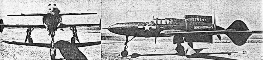
ONE of the most unusual Army Air Forces research projects to be revealed to the public by the Air Technical Service Command is the Curtiss XP-55 Ascender, a tail-first, pusher fighter. Canards, as this type craft are known, are not new for it will be remembered that the Wright Brothers made their first flight in a tail-first biplane. During the early days of World War I, however, the familiar tractor planes gained favor and until this day have reigned supreme. Nevertheless, numerous advantages are claimed for military planes of this pattern and Curtiss' experiments along these lines were welcomed by the Army Air Forces.
Paralleling the trend in real aircraft, canard pusher models were once popular but gave way to conventional types with propeller in the nose and vertical and horizontal stabilizers at the tail. Spiral and directional stability are major problems in this design craft but because of its generally good overall setup, the XP-55 affords a remarkable subject for experimentation in tail-first models. The only major change from scale is the suggested enlarged front elevator which has dihedral added to achieve maximum stability.
Little difficulty will be experienced in building a model Ascender. Balsa wood is used and the little ship is fabricated in the conventional way. Exercise care in following details and you will soon be the owner of an attractive flying model of most unusual design.
FUSELAGE - Easiest and most accurate means of constructing the fuselage is by the use of bulkheads and keels. Measure the size of parts from the plan and cut bulkheads and keels from sheet balsa; note that only half bulkheads are shown so make two of each. Pin top and bottom keels over the side view of the plan and attach half the bulkheads and one side keel. Now remove this structure from the jig and add the remaining bulkheads and keel. Stringers are firm square stock and they should be placed in pairs, one on each side in respectively similar positions to keep from pulling the body out of line.
Where the wing fits in, curved 3/32 sheet pieces are fitted to the fuselage sides to conform to the wing surface curvature; place these accurately because they aid in aligning the wing correctly. The front elevator mount is 1/16" balsa and is carefully fitted at the exact positive angle of incidence shown. The elevator halves are later butted against these.
At front and rear of the fuselage, laminated pieces of balsa are shaped so as to fit to bulkheads A and I. The nose plug has a .035 diam. music wire hook in it to hold the rubber motor. The nose is removable, as is the tail plug which is removable from the laminated tail block. A 1/32" disc of plywood is used for the face of the plug and the rest is laminated squares of balsa. Drill a tiny hole through the plug for the propeller shaft and then cement washers to either side.
WING - Front elevator and wing are constructed in a like manner. Ribs are cut from sheets of the thickness indicated for each on the plan; make two of each. Leading edges and spars are likewise cut from sheet balsa. To determine the taper, measure the depth at the center and tip ribs as well as the overall length and cut them out accordingly. Remember to build right and left panels of each surface. Join the wing halves by raising the tips to the proper dihedral and cementing rib No. 1 firmly into position. When assembling the elevator, incline the inner rib E-1 so that when it is butted against the fuselage mount the dihedral will be as indicated on the side view.
CONTROL SURFACES - Fuselage fins and wing tip rudders are made next. For a flying model it is suggested the fuselage fins be made flat to obtain the fullest stabilizing action from them. Scale builders will note that crossection shapes are given to enable them to duplicate the real plane more exactly and in this case the structure should be altered accordingly. Build the two fins, top and bottom, as well as the wing tip rudders from 1/16" thick stock of the width indicated. Cement joints firmly so they will not warp.
LANDING GEAR - Any flying scale model must have a strong landing gear and the wire struts suggested are very strong and practical. The front fork is made from two pieces of wire of about .035 diam. soldered together. With needle and thread sew the front strut to bulkhead B. Rear legs are of similar wire and the struts are bent to join rib No. 4 and the spar and leading edge. Be sure to make a right and left one and then lash them in place with thread. Coat the areas adjacent to landing gear attachments with cement to strengthen the structure. Scale effects for making the gear look more realistic are left until later.
COVERING - Sand all of the frames with fine grade paper before beginning to cover. Colored tissue is both attractive and light and it is recommended; attach it with banana oil or light dope. When covering the fuselage, use numerous small sections of tissue to avoid unsightly wrinkles; these must be neatly lapped, however. Tail surfaces and wings are covered using a separate piece of tissue for each side of each part. The covering may be tightened by lightly spraying with water, but apply no dope until all the ship has been assembled.
ASSEMBLY - To assemble the parts follow this outline: First fit the wing into the recess in the fuselage and cement it firmly; if the parts have been made accurately, alignment and incidence will automatically be correct. Next butt the elevators against the fuselage mounts at the dihedral and incidence angles noted; cement them firmly. Now the fuselage fins may be installed directly over the vertical centerline. Wing tip rudders are cemented fast and they are exactly parallel to the centerline.
DETAILS - Scale effects are the features that "make" a model; however they must be skillfully executed to achieve maximum appearance value. Make the cockpit enclosure from two pieces of thin celluloid (cleaned celluloid obtained by boiling photo film in water to remove the emulsion); structural details are represented by contrasting strips of dark tissue doped to the canopy. For greater realism rubber tubing of the correct diameter is slipped on the landing gear struts. Tiny auxiliary struts may be made from thin slivers of bamboo, and the covers that close the wells when the gear is retracted are 1/32" balsa covered with tissue to match the covering. Gun blisters, exhausts and the like are fashioned from scraps of balsa. Control surfaces are represented by thin strips of black tissue doped to the covering. Numerals, star insignia, etc., are made from colored tissue if decals are not obtainable.
PROPELLER - Details of the enlarged propeller are given. Carve a right hand prop from hard balsa and then fit a soft balsa spinner over the hub. A .035 diam. music wire shaft is installed. Remember to place several washers on the shaft between prop and tail plug to reduce friction.
POWER - Most models will require six strands of 1/8" flat brown rubber for power but a heavy model may require eight. To assure maximum power and longest life from the rubber, lubricate the strands with a mixture of tincture of green soap and glycerin, which are obtainable at drug stores. Hook the rubber strands to the prop shaft and then slip them through the fuselage where they are held by the hook on the nose block. The little ship is now ready to be flown.
FLYING - Launching a pusher model is a problem so rise-off-ground flights are advisable. Wind the motor a few times and permit the model to make short hops. If it appears to stall, add ballast to the nose (tiny pieces of lead, BB shot, etc.); should it fail to climb, tilt the thrust line down by inserting a sliver of wood between the bottom of the tail block and plug. The amount of turn while the model is in powered flight may be controlled by offsetting the thrust line right or left in a similar way. Large shallow turns to the right are generally most desirable. As flights improve, gradually increase the power. The Ascender is a trim little ship, light in weight and swift in flight - you are sure to be proud of it!
VICTORY
Scanned
from July, 1945
Model Airplane News
![]()
![]()
![]()
![]()
[ Home ] [ Previous Plan Pages ] [ Special
Things ] [ Earl Stahl Plans ]