The Plan Page
[ Home ] [ Previous Plan Pages ]
[ Special Things ] [ Earl Stahl Plans ]
gt-hunter1@home.com
Test the
pusher theory by building this Plane on the Cover model
by EARL STAHL
The search for superior fighting aircraft is an endless one for all warring nations. Constantly poring from engineers' drawing boards and from aeronautical laboratories is an endless stream of ideas ranging from minor modifications for successful craft already at grips with the enemy to radically new craft boldly striving for supremacy over anything the foe, can hurl into the conflict.In reality, only a small fraction of the ideas conceived prove wholly practical in the end. Such is true of literally thousands of designs for aircraft submitted to the air arms of our Army and Navy. Usually from competitions in which manufacturers are invited to offer designs for specific types of craft, the armed forces select several of what appear to be the most promising projects for actual construction and exhaustive tests. Of these only a very few ever attain quantity production for eventual action in enemy skies.
Reasons for a plane's failure to make the grade are numerous and varied. Perhaps the new ship is of inferior performance, below the expectations of the designers. Possibly it is possessed of unstable flight characteristics, spins too viciously, or is abnormally dangerous. Occasionally an otherwise satisfactory type is plagued by grief brought about by a troublesome engine or faulty accessories. Many times volume construction or cost difficulties doom the ship to oblivion. On the other hand the design may be entirely satisfactory but is shelved because its small margin of superiority over existing types makes reconversion impractical.
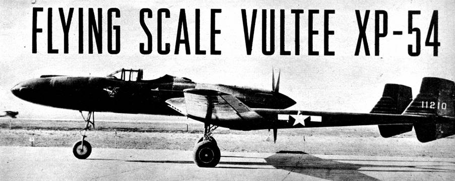
Such a plane is the Consolidated Vultee XP‑54. This unconventional fighter has been under test by the Army Air Forces but was discarded in favor of fighters now in, or going into production. No reason for abandonment of the XP‑54 has been given.
A plane of very striking appearance, it incorporates a number of unusual features. Driving the four‑bladed pusher propeller is an experimental Lycoming liquid cooled engine of great power. One of the pet gripes of pilots who condemn pusher aircraft such as this one (and justly so!) is that when leaving the ship in an emergency, the body would in all probability be hurled into whirling propeller blades. This problem was solved in the XP‑54 by equipping it with an ejector which casts the pilot beyond the arc of the prop and also the tail surfaces. Situated midway on the pod like fuselage, forward of the engine and inverted gull wing, the pilot's cockpit affords unusual visibility, a decided asset. It is pressurized to enable the pilot to hunt and fight at great altitude. Four cannon of probably 20 mm bore are provided for in the long nose.
Because of its unusual yet practical design, the Vultee XP‑54 makes an excellent flying scale model. The drawings are accurately scaled and will serve as the basis for both a flying or exhibition model. Construction of the miniature will not be difficult if drawings and details sketched here are followed closely. Balsa wood is used throughout and quick drying colorless cement is the adhesive. Incidentally, the reward for neat, accurate work is finer appearance and better flights!
The model's large size and odd shape made it necessary to extend the side and top views over two pages each. Simply match the pages together so work can be done atop them since most parts are shown full size.
Crossectional shape of the fuselage is cylindrical so most bulkheads are circular. The keel and bulkhead method of construction is employed and each of the four keels (top, bottom and two sides) and the bulkheads are cut from 1/16" sheet balsa. Two of each bulkhead type are cut except No. 3 which requires eight. To assemble, pin top and bottom keels in place over the side view, attach half the bulkheads to their respective positions and cement a side keel to place. When dry, remove from the plan and add the rest of the bulkheads and remaining keel. Stringers are 1/16" sq. firm stock and are fitted to the notches. Where the wing fits in, curved 1/8" sheet pieces are fitted exactly as shown to conform to the top surface of the wing; place these accurately since they aid in aligning the wing accurately.
At front and rear of the fuselage, laminated pieces of 1/8" sheet are shaped so as to fit to bulkheads No. 1 and No. 7. The nose block has a .035 diam. music wire hook in it to hold the rubber motor, and a tiny loop in the front into which a mechanical winder can be hooked for storing up maximum power when flying. The nose is removable as is the tail plug which fits into the laminated tail block. A disc of 1/32" plywood forms the front of the plug and the rest is laminated squares of 1/8" sheet. Drill a hole through the plug for the prop shaft and cement washers to either side.
Only the right wing is shown so it is best that the left wing plan be made at once. Ribs are 1/16" sheet accurately cut to the shape given. The main spar is 1/16" x 1/8" balsa while the landing gear one is 1/16" x 3/16". Build right and left panels individually and without dihedral. Once the frames are complete, spars and leading and trailing edges are cracked and the tips raised 2‑1/8" while the inner section remains flat; recement the joints well.
Booms fit to wing ribs No. D and are built like the fuselage except that the center keel is one frame trussed with 1/16" sq. strips for greater strength. Lay out the keels over the side view and then add the bulkheads and stringers which are 1/16" sq. strips. Remember two booms are required.
If wings and booms have been made accurately, they will assemble correctly without too much trouble. Note on the side view how they sweep upward in the rear (about 3* measured relative to the flat bottom of the rib and the center stringer of the boom), and on the top view how they tow in. Easiest way to assure complete accuracy is to lay out the booms on the wing drawings and assemble them over these layouts. Be sure to attach them firmly using plenty of cement.
Tail surfaces are easily made from 1/16" x 1/8" outline strips and 1/16" sq. ribs. Note how additional 1/16" sq. strips are placed at each side of each rib to strengthen them and give the streamline crossection.
The landing gear must be very strong and the wire struts suggested are very practical. The front fork is made in two pieces from wire of about .035 diam. and are soldered together. With needle and thread sew the front strut to bulkhead No. 4. Rear legs are of similar music wire and the tops are bent to join ribs No. D and the spar. Be sure to make a right and left one and then lash them in place with thread. Coat the adjacent areas to the landing gear attachments with plenty of cement. Scale effects for improving the landing gear appearance are easily represented with rubber tubing and scraps, but this is not done until later.
The following sequence is suggested as best for continuing construction of your XP‑54. Cover the wings from rib A outward including the booms which were previously attached. Colored tissue is best used since it is both attractive and light and thin dope or banana oil is the adhesive. When covering the fuselage, use a number of small pieces of tissue neatly lapped to help avoid unsightly wrinkles. Incidentally, don't cover any of the area below the wing mount strips until after the wing is in place. Tail surfaces are covered using a separate piece of tissue for each side of each part. The covering may be tightened by lightly spraying with water at this time, but apply no dope until the ship is entirely assembled.
Wings are assembled by slipping them into position and cementing fast, but first be sure of their proper placement. It is suggested that the fuselage be blocked perfectly level with the bottom exactly 7/16" above the level surface of the work bench. Now, with the lowest portion of the boom keels (under the gull of the wing) touching the bench, the dihedral at each tip measuring 1‑1/8" and the extreme rear of the booms raised 11/16", the alignment should be correct. All this may sound difficult but it really isn't; use small blocks of wood, pins, bottles and ingenuity to hold the parts in place to achieve the proper setup. (Note: holes drilled in the assembly table for the landing gear to slip through permits the plane to be assembled in this manner; otherwise all dimensions should be lengthened equally to clear the gear above the layout table.) While the little ship is jigged up, cement the stabilizer fast noting that a line through the leading and trailing edge of it is parallel to the center stringer of the boom. Rudders are likewise cemented on, not at the angle of the booms but parallel to the line of flight (centerline). All uncovered parts should now be finished and then one or two coats of clear dope applied.
Now for the lesser items. Wheels are easily made from balsa or they may be purchased; glue washers or bearings to them so they will revolve accurately. For added realism rubber tubing of the correct diameter is slipped on the wire landing gear struts. Tiny auxiliary struts are slivers of bamboo, and the covers that close the wells when the gear retracts on the real ship are 1/32" balsa covered with tissue to match the model's coloring. The cockpit enclosure is thin celluloid (cleaned photo film) and it should be made in three sections to shape it properly; avoid cement smears when attaching to the model. Cannon blisters, radiators and like details are made from wood scraps and black tissue. Control surfaces are outlined with thin strips of black tissue. U.S. star insignia, numerals and the like may be made from colored tissue but decals are far less trouble.
A flying model requires an enlarged propeller, and details for the four‑bladed one and spinner are given on the drawings. Use hard balsa for the prop and a soft grade for the spinner. Music wire .035" in diameter is bent as indicated for the prop shaft. Be sure to place several washers between tail plug and prop so it will turn freely.
Six strands of 1/8" flat rubber should be right for most models, but with different weight ships this may vary. Lubricate the rubber with a mixture of tincture of green soap and glycerine to attain most power and longest life from the strands.
Skillful handling and correct adjustment are required to get maximum flight performance from any model. Select a place where the ship will not get damaged while flying it ‑ a branch of a tree or side of a building is scarcely a suitable landing place. First make shoulder high test glides adding weight to nose or tail to correct a tendency to stall or dive. Launching a pusher is a problem so rise-off‑ground flights are in order. Try a few turns on the rubber motor at first, gradually increasing the number as flights improve. Offsetting the thrust line is an effective way of adjusting unstable power flight attitudes and controlling the amount of circle. Treat your XP‑54 with care and you will be rewarded with a fine flying, attractive miniature.
VICTORY
Scanned
from May, 1945
Model Airplane News
![]()
![]()
![]()
![]()
[ Home ] [ Previous Plan Pages ] [ Special
Things ] [ Earl Stahl Plans ]