|
THE WACO E One of the Most Realistic and Finest Flying Scale Models Ever Designed - A Replica of a Famous Plane By EARL STAHL |
|
The Plan Page
[ Home ] [ Previous Plan Pages ]
[ Special Things ] [ Earl Stahl Plans ]
gt-hunter1@home.com
|
THE WACO E One of the Most Realistic and Finest Flying Scale Models Ever Designed - A Replica of a Famous Plane By EARL STAHL |
|
WACO planes are known throughout the world for their fine performance, stamina and distinctive appearance. Newest member of the Waco family of planes is the model "E", a five passenger biplane which is rapidly attaining a full measure of popularity on the skyways of the nation.
Featured in its design is a radical new engine cowling which is an integral part of the fuselage. This eliminates the usual break between the cowling and body and adds to the plane's beauty and performance. A small flap at the bottom of the cowl permits the pilot to maintain any desired engine temperature.
The Waco "E" is available powered with several engines of varying power. The Jacobs engine of 330 horse-power affords a cruising speed of 177 m.p.h. and a rate of climb of 1,170 ft. per min. Fuel stored in synthetic rubber fuel tanks is sufficient for a non-stop flight of 1,100 miles. Electrically operated flaps are employed to slow the speed of landings.
Structurally and proportionally the Waco "E" is an excellent design for a flying scale model. The original proved to be a fine performer; it takes to the air in steep, thrilling spirals and makes flights of over 50 seconds. This model can really "take it" too, for the biplane type of construction is very rugged. Since the size is rather small, it is important that the weight of the various parts be kept at a minimum. The manner of construction is entirely conventional, so little difficulty should be experienced as your Waco takes form.
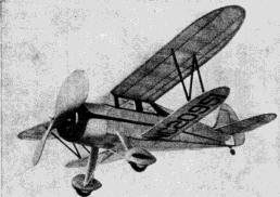
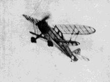 It looks and climbs like a pursuit plane |
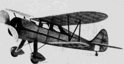
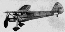 The construction is light but sturdy |
 A large area propeller gives it a lively performance |
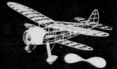 The uncovered frame reveals fine structure |
Fuselage
A simple rectangular frame is the backbone of the fuselage structure; it is shown lightly shaded on the plan. Work directly over tracings of the plan and build two side frames, one over the other to make certain that they are identical. Medium grade wood should be used; the longerons are 3/32" square and the uprights are 1/16" x 3/32". Stick pins on both sides of the longerons and crosspieces to hold them in place until the cement is dry. Separate the frames with a thin razor blade, should they stick together, then invert them over the top view. Cement 1/16" x 3/32" crosspieces into position at the center of the body and when dry draw the backs together and place the remaining cross-pieces. It will be necessary to crack the longerons in order that they can be pulled into position at the front. Check continually to assure a correctly aligned structure.
Because of the rather simple structure of the prototype, few fuselage formers are required. The formers are shown full - size on the drawings and they are cut from soft 1/16" sheet balsa. Cut the notches to receive the stringers and then cement the formers to place. From 1/16" sheet cut two top and two lower wing ribs; the shape of these being shown on the side view, first page of plans. Cement the upper wing ribs directly atop the longerons and the lower ones to the sides of the frame, adjacent to the gussets provided at that point. Make certain that the ribs are at the positions indicated and at the exact angle shown. Since the stringers are merely fairing strips, they should be soft balsa. Draw the 1/16" square pieces between fine sandpaper to reduce their size to about 1/20" square. As shown by the view of a typical fuselage cross-section, the stringers are cemented directly to the under-frame, except where there are sheet balsa formers, of course.
The nose is covered with sheet balsa. A soft grade of 1/32" sheet is used and all of the shaded area, as shown on the plan, is covered. Three or four individual pieces will be needed for the job. Cement the covering to the frame using pins and rubber bands to hold the pieces in place until dry. The front of the cowling is made from several balsa discs which are cemented together. First cut the 1/4" thick disc; it is a solid piece except for the hole in the center for the nose plug. The remaining rings are cut from 1/8" sheet and all are glued together. Cement the unit to the formers of section A - A and when dry roughly cut to shape. Use sandpaper to finish the job of making it fit exactly to the sheet covering. Sand the whole nose thoroughly. The nose plug and crankcase are also made from laminated balsa discs. Cut both to shape making sure the nose plug fits neatly to the crankcase. The crankcase is cemented to the cowl-front and the nose plug will be needed later.
Tail Surfaces
The tail surfaces must be kept light since any excessive weight behind the center of gravity must be balanced by additional weight in the nose. The stabilizer is built in one piece so a complete plan must be made; build directly atop the plans. Cut the outline shapes from 1/16" sheet and pin them to place over the plan. The spars and ribs are 1/16" square stock. When these flat frames are dry, lift them from the plan and cement soft 1/16" x 1/32" strips to both sides of the ribs. These strips are later cut to a streamline shape. Trim and sandpaper the stabilizer and rudder to complete their construction.
Wings
Construction of the wings is very easy. Full size patterns of all the different ribs are given; except where otherwise noted, they are cut from 1/32" sheet. It will be necessary to cut ten of the T - 1 ribs, and two each of T - 2, T - 3 and T - 4 as well as eight of B - I and two of B - 2. The wing tip pieces and trailing edges are cut from 3/32" sheet. Assemble the tips and then remove them from the plan for the time being. Pin the trailing edges into place; the ribs likewise. 3/32" square strips set on edge form the leading edges. Make a "vee" cut in the tip where it joins the leading edge so the fit will be better. Raise the center of the tip about 3/32" and then cement fast. All of the spars are medium grade 1/16" square stock. After the completed frames have been in the jigs long enough to prevent any warping, they may be removed and trimmed to shape. The trailing edges are smoothly tapered and the leading edges rounded; tips are neatly tapered, too.
Landing Gear
The wire landing gear strut should be formed at this time. It will first be necessary to make a full-size sketch of the wire which is shown 3/4 size on the front view. Bend the strut from .028 music wire and be sure to make the axles long enough to accommodate the wheel pants. With thread neatly bind the wire to the body at the position indicated.
Although the remainder of the landing gear is not attached at this time, the parts can be made. The wide struts that cover the wire are made from extra hard 1/8" sheet balsa. They are streamlined and a 1/16" deep groove is cut on the inside to hide the wire. The method of making the wheel pants is detailed; roughly cut the pants to shape and then finish with sandpaper. Wheels can be made of balsa, also, but they must be of thin cross-section to fit within the pants. Cement bearings to the wheels so they will revolve smoothly.
Covering
A good covering job can not be made if the frame underneath is rough or irregular; the importance of this can not be overemphasized. Use very fine sandpaper and work over all of the frame that will touch the paper. The corners of the fuselage longerons are sanded round. Once you are satisfied that the frame represents the best of your ability, the model is ready to be covered.
The author finds the regular colored tissue to be the superior covering material for flying-scale models since it can be worked into attractive color schemes and it is much lighter than colored dope. Orange with black trim is the color of the model shown in the photos which accompany this article. Many attractive color schemes can be arranged, provided, of course, a light color is used as the base with a darker color for the trim - obviously a black model can not be trimmed with yellow tissue, etc.
The cellophane side windows must be cemented to place before the fuselage is covered; the whole area below the top wing rib being covered with cellophane since the window outlines are formed by the tissue covering. Banana oil or light dope should be used to stick the tissue to the frames. Cover the fuselage first, cowling included; using many individual pieces to prevent wrinkles. Attach only the outsides of the area being covered. Cover the wings in a similar manner for they will need four or five separate pieces to do a good job. Neatly trim the excess paper with a sharp razor blade. When covering the tail surfaces, care must be exercised to keep the covering from touching the center spar. Once all the parts are covered they are lightly sprayed with water to shrink the tissue. Pin the wings and tail pieces to a flat surface to keep them from warping.
Following is the recommended method of cutting and applying tissue trim: First, a paper pattern of the design is cut to the exact desired shape; for instance, the design on the upper part of the fuselage of the original model was cut to shape, windows, etc., included. This pattern is then traced on a sheet of writing paper. Two sheets of black tissue are placed under the writing paper and all three sheets are held to the work board by thumb tacks. Now use a sharp, pointed razor blade and it will be an easy matter to neatly cut the tissue. Make use of a straight-edge when cutting stripes, etc. To apply the trim it is best to first lay it in the exact position desired, and then brush thin dope over it. The method, as described, is used to make all paper decorations, stripes, license numbers, etc.
Assembly
The various parts are now assembled. A half windshield pattern is given on the plan; cut a complete paper pattern to make certain that it will fit your model before cutting one from celluloid. Cement the windshield to place, being careful to prevent cement smears. The stabilizer is placed in position directly on the top longerons. Offset the rudder a bit to counteract torque. The rudder should be perpendicular to the stabilizer. Attach the top wings - this will be all easy matter since their exact position and angle have already been determined. Elevate the tips 1-1/8" for the proper amount of dihedral. Bottles, cans or the like can be used to hold the wings until dry. The lower wings are placed exactly parallel to the top wings. "N" struts are made from pieces of 1/16" x 1/8" streamlined balsa. Assemble the struts in a jig; they are a bit longer than shown on the side view since they set at an angle between the wings. Use the "cut and try" method to fit the struts most accurately. A coat of clear dope can be brushed on the entire model. Do this job in a dry room to prevent "blushing" and exercise caution to prevent any warps. Finish the landing gear next. The wide balsa struts which were made previously are fitted to the wire struts. Do not cement the tops to the fuselage; fill the groove with cement and then cover the strut with tissue. The back and center struts are rounded bamboo. Paint the wheels before placing them within the pants; the pants being coated with several applications of dope to prepare them for a good paint job. Cement the pants to the landing gear struts.
Minor details are usually the features that "make" the model. Seven half - cylinders are required to represent the engine. Thread wrapped about rounded pieces of balsa can be used effectively. Fit the cylinders accurately and neatly within the cowl front and then paint the inside of the nose black. Push rods can be rounded bamboo or straight pins. Make the license numbers from tissue by the method previously described. Wheel pants, landing gear struts, and the "N" struts are color doped. Control outlines, flaps, a door, etc., can be represented by strips of black tissue. The tail wheel, inter-plane wires and numerous other detail can be added to improve the appearance of your model without seriously impairing the flight ability.
Propeller
Good flights can not be expected unless the model is equipped with an efficient propeller. Select a hard block 6-1/2" x 1-1/2" x 1" for the prop. Drill the tiny bole for the prop shaft, then cut the blank as indicated. A right-hand propeller is carved; thin the blades as much as possible while still retaining the required strength. Broken lines indicate how the thickness of the hub is reduced; also round the tips of the blades. Several coats of dope with light sanding between will make a smooth finish possible. A free - wheel gadget should be used and the simple "dog - tooth" type, as shown on the plan, is suggested; it is made from 1/64 brass. Cement washers to the back of the prop and to the front and back of the nose plug. The prop shaft is .034 music wire and it has a loop on the front to which a winder can be attached. Both propeller and nose plug are color doped.
The test model weighed 1.7 oz. complete and it was powered by four strands of 3/16" flat rubber. The amount of power required for other models will be determined by the weight and the performance desired. Rub lubricant on the rubber strands but remove the excess to prevent its splashing on the sides of the fuselage. A round bamboo pin in the rear of the fuselage holds the rubber motor. Your Waco is now ready for the initial flights.
Flying
The original model was a grand flier and, after more than forty flights, is still in good condition except for a few patches in the covering.
In testing the Waco, it should be flown in calm air over a grassy field. The descent from a hand glide should be flat and smooth but a small weight in the nose or tail will correct any error in balance. Next test for stalling or improper circling by launching with about 30 winds in the rubber motor; any error here can be corrected by offsetting the thrust line so the prop pulls downward to prevent a stall or to the right or left to control circling. Other adjustments are effected by warping the tail surfaces slightly.
Now your ship is ready for a real flight. Stretch the rubber motor and store up power with a mechanical winder. When you release her, she will show you how a really fine model should fly.
Scanned From July 1940
Model Airplane News
![]()
![]()
![]()
![]()
[ Home ] [ Previous Plan Pages ] [ Special
Things ] [ Earl Stahl Plans ]