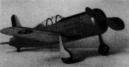
 The completed model, realistic in detail |
 The wide tread helps take‑offs and landings |
The Plan Page
[ Home ] [ Previous Plan Pages ]
[ Special Things ] [ Earl Stahl Plans ]
gt-hunter1@home.com
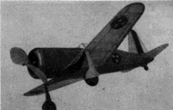
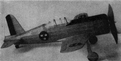
The completed model, realistic in detail |
The wide tread helps take‑offs and landings |
The Vultee Vanguard
How to Build a High Performance Flying
Scale Model of Uncle Sam's Latest Fighter
By EARL STAHL
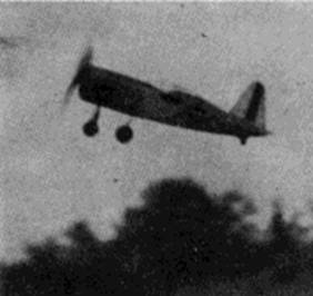
Here's the little plane climbing skyward.
It's attitude denotes stability and grace.
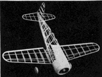 The structure is simple but strong. |
 The large, high-pitch prop gives fine performance to this beautiful ship |
THE Vultee Vanguard 48C is one of the most beautiful airplanes ever designed and looks like what a pursuit plane "should look like." Although never given the opportunity to prove itself in battle it will always be a favorite design for the model builder. The AAF has purchased several known as the Vultee P-66.
Upon its introduction it was one of the fastest and most heavily armed fighters in the world and it was designed expressly for "serviceability," with large panels, easily removable, giving access to armament, controls and installations. It can be stripped down for servicing in two minutes flat, and gun barrels can he changed without removing the guns. In addition to heavy armament, a series of small bombs may be carried, making it one of the world's first fighter - bombers.
When powered by a double row Pratt and Whitney Wasp engine this single seater has a maximum speed of 358 m.p.h. Its cruising speed is 316 m.p.h., and it lands at 73. The fuel load of 240 gallons is sufficient to keep the plane in action about 2-1/2 hours.
The model has been accurately reproduced and is worthy of any effort expended on its construction. It is not only attractive as a display model but it is also a speedy, stable flyer. A small amount of wing area and the large fuselage naturally limit the model's capacity for making flights of long endurance; however, it will afford real satisfaction with the many realistic flights it is sure to make.
Fuselage
Begin the construction by making the keel pieces. Trace the top and bottom outlines of the side view to get the correct shape; the bottom keel is a continuous piece extending from nose to tail and the top keel is two separate pieces. Average depth of the keels is about 3/16"; they are cut from 1/16" sheet balsa. Bulkheads are shown full size on the plan and they, too, are cut from medium grade 1/16" balsa sheet. Two of each are required. It will be noticed that only a few of the bulkheads have notches for all of the stringers. Cut out the notches shown and mark the positions of the others which will be cut later,
Pin the keel pieces into position over the plan and begin actual assembly of the fuselage. Temporarily cement a piece of 1/16" x 3/16" balsa between the top keels to join them at the opening created by the cockpit. Cement half of the bulkheads to their respective positions and when dry remove from the plan and attach the remaining ones to the other side. Align the bulkheads accurately so they are exactly perpendicular to the keels. Cement the two 1/16" square stringers to each side where the notches are provided, being careful not to draw the fuselage out of line. Place the remaining stringers, cutting the notches as required with a sliver of a razor blade. Once a stringer is attached to one side, always place another in the corresponding position of the other side. After the stringers are all attached, the temporary brace at the cockpit as well as the portion of the bottom keel between section 2 and section 5 should be removed.
The engine cowl and top of the fuselage back to the cockpit are covered with 1/32" sheet. Make a paper pattern of the cockpit shape and cut the sheet balsa accordingly before cementing to place. Pins and rubber bands will help keep the sheeting in place until the cement is dry.
The cowl front is made from four discs of 1/8" thick balsa which are cemented together. The back disc, adjacent to bulkhead No. 1, is solid except for the 5/8" hole for the nose plug; other discs have the centers removed to the extent indicated on the plan. Cement together with the grain of each opposite that of the adjacent discs. Attach the unit to the first bulkhead and when dry, roughly cut to shape. Finish by sandpapering the cowl and sheet balsa covering. Details of the nose plug are indicated. The removable nose plug should be made to fit neatly to the crank case which is cemented within the cowl front.
Tail Surfaces
Construction of the tail surfaces is easy. Both the stabilizer and rudder are built in a similar manner. In the interest of greater strength the stabilizer is built in one piece. Outlines are cut from 1/16 " sheet and the ribs and spars are 1/16" square strips. When dry, the frames are removed from the plan and very soft pieces of 1/16" square cemented to both sides of the ribs. These are cut to a streamline shape when the adhesive has hardened. Trim and sandpaper the surfaces to the final shape. Surfaces constructed in this manner are light yet sturdy.
Wing
It is necessary for the wing to be of strong construction since the landing gear is attached to it. Make a left wing plan so both halves of the wing can be assembled directly over full-size plans. Ribs W1 to W4 are cut from medium grade 1/16" sheet while W5 to W8 are 1/32" sheet. Pin the ribs to place over the plan and attach the spars and leading and trailing edges; however, the spar to which the landing gear struts are attached is not placed in position until the dihedral has been added. Center ribs W1 should be slanted so the dihedral will be correct when the wings are joined. Tips are cut from 3/32" sheet. Join the wings solidly using plenty of cement; dihedral should be 2-1/16" at each tip. Attach the 1/16" x 3/16" hard balsa spar and re-enforce the joint necessitated by the dihedral. Trim and sandpaper the entire wing.
Landing Gear
A landing gear of the type used on the "Vanguard" always presents a problem to the model maker. However, the landing gear developed for this model is easy to make, accurate in appearance and it will take all the abuse the model can give. .040 music wire is used and the top is bent in such a manner as to join the lower wing spars and rib No. 4. Make a right and left strut. With thread bind the struts to the spars and then use a needle and sew right through rib No. 4 and about the wire. Apply several coats of cement to the thread wrappings and adjacent areas. The rubber tubing covers are not slipped on until the wing has been covered.
Wheels may be purchased or they can be made from laminations of 1/8" thick balsa. Cement washers to both sides of each wheel so they will turn freely and accurately.
Propeller
Select a very hard balsa block 1" x 1-5/8" x 8-1/2" for the propeller. Drill the tiny hole for the prop shaft and then cut out the blank as indicated on the plan. Carve a right hand prop. Finish the back surface of the blades first, then cut away the front until the blade thickness is as desired. Reduce the thickness of the hub and round the tops of the blades in a manner similar to the prop in the photos. Sand to a final, smooth shape. Apply several coats of clear dope with light sanding between each. Cement washers to both sides of the prop shaft hole and then apply color dope.
The prop shaft is bent from .040 music wire. Slip the nose plug which was made previously, and propeller, in place with several washers between them. If a free‑wheel device is to be used, the end of the shaft is bent as indicated; otherwise the end of the shaft is bent at a right angle and forced into the hub. The loop at the front of the shaft serves as a place to hook a mechanical winder.
Covering
First step in preparing for a fine covering job is to thoroughly sand every bit of the frame work to remove all flaws and roughness. Since only those members of the fuselage which run from nose to tail should touch the covering, it is necessary to sand the bulkheads to a scalloped shape. This is done with a piece of fine sandpaper wrapped about a pencil or similar round object.
Colored tissue is used for all of the covering and decorations. Red and black with blue and yellow trim is the color of the plane shown in the photographs. Cover the wing first, using banana oil or light dope to stick the tissue to the frames. Wings are covered from the second rib to the tips. Attach only the extremities of the area being covered. Tips require separate pieces to help avoid wrinkles. Tail surfaces are covered in the same manner. Since the fuselage is circular in cross-section, it is necessary to use many small pieces of tissue to help prevent unsightly wrinkles. The cowl and other sheet balsa covered parts are tissue covered, too. Spray the covering with water and pin the surfaces to a level position to keep them from warping. The clear dope is NOT applied to the covering until later.
Assembly
Following is the recommended procedure for assembling the Vanguard: Cement the wing to the position indicated on the plan; if the structure has been reproduced accurately, the angle of incidence will automatically be correct. Finish the under section from wing to fuselage with pieces of 1/16" square. Wing root pieces are cut from 1/16" sheet and they are cemented between the wing and fuselage. The 1/32" sheet fillet pieces are shown on the plan. This pattern indicates the shape of the fillets on the original model but most models will vary somewhat so paper patterns should be made to fit your model exactly before the sheet balsa ones are cut. Once the fillets are cemented to position, the several small openings at the junction of the wing and body should be "filled-in" with scraps of soft 1/16" sheet. Sand smooth and cover the fillets with colored tissue. To set the stabilizer in position it will be necessary to temporarily cut the rear of the fuselage and bulkhead No. 9; attaching the stabilizer at a slight negative angle. The rudder is attached exactly perpendicular to the stabilizer, and it is off-set 1/16" to counter-act torque. Small tissue fillets at the tail surfaces will enhance the model's appearance. Moisten any wrinkles and permit to dry before applying a coat of clear dope to the entire model.
Addition of the various minor details completes the construction. The cockpit enclosure is made from thin sheet celluloid. Make accurate patterns before cutting the celluloid; avoid cement smears when cementing to place. Slip the rubber tubing (as used on electrical appliances, etc.) on the wire struts. Wheels are held to the axles by washers soldered to place. The wheel covers are cut from 1/32" sheet or stiff paper; they should be covered with colored tissue to match the other parts. Seven base-relief cylinders are cemented within the cowl to represent the twin-row Wasp. Color the cylinders and cowl front black. Control surface outlines are black tissue strips, as are the cowl flaps. The Swedish insignia on the original model was made with black tissue, too. A tail wheel and other details found on photos of the real ship can be incorporated to make your Vanguard more attractive.
Power for our model is supplied by 10 or 12 strands (5 or 6 loops) of 1/8" flat, brown rubber. Hook the motor to the prop shaft and drop the other end through the fuselage. It may be necessary to remove a small portion of the covering in order to get the strands in position to be held by the removable bamboo pin. The model Vanguard is now ready for its initial flights.
Flying
Select a calm day and a grassy field for the first tests. First, try a few hand glides to ascertain the correct balance; a small weight in the nose or tail will correct a tendency to stall or glide too steeply. Once the balance seems right, wind the motor a few turns and launch. The flight should be smooth without a tendency to bank excessively. Tilt the nose plug right or left to control the circle; a bit of down-thrust will remedy a stall while under power. Gradually increase the number of turns and make any further adjustments. Stretch the rubber and store up power with a mechanical winder for maximum flights.
The author's ship was thoroughly tested and proved to be a good flyer. It is, however, sensitive to every adjustment so any change must be made with skill and care.
Scanned from Flying Scale Models
by
Air Age Publications
![]()
![]()
![]()
![]()
![]()
[ Home ] [ Previous Plan Pages ] [ Special
Things ] [ Earl Stahl Plans ]