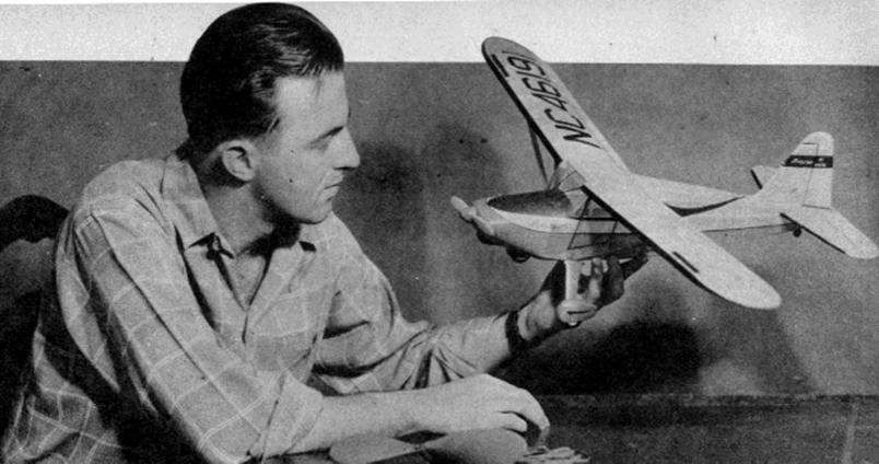
The author displays his model. Note the flying and scale propellers, finish and scale details.
The Plan Page
[ Home ] [ Previous Plan Pages ]
[ Special Things ] [ Earl Stahl Plans ]
gt-hunter1@home.com
The author displays his model. Note the flying and scale
propellers, finish and scale details.
STINSON 125
By Earl Stahl
THIS STINSON IS THE FIRST OF A SERIES OF FLYING SCALE MODELS OF POSTWAR PLANES. THIS FEATURE WILL BE BROUGHT DIRECTLY FROM THE DESIGN DEPARTMENTS OF THE MANUFACTURERS.
THE eyes of the aviation world are gradually becoming focused on the postwar personal plane. It is only natural that the thousands upon thousands of war‑trained pilots and crews will want to continue to fly once they return to a more normal, peacetime existence. And the aircraft industry with its tremendous facilities for the production of fighting craft will undoubtedly project its experience in design and construction into the family plane field. With these conditions existing, private flying will boom.
In all probability, the new private planes will follow closely the prewar patterns but with many refinements for safety and comfort.
Such a plane is the new Stinson "Voyager 125" which inherits the appearance, safety, and reliability of the prewar "Voyager" as well as the ruggedness and utility of the remarkable Stinson "Flying Jeep," workhorse of the Army for observation, liaison, and ambulance work.
Powered by a 125 horsepower Lycoming engine, the new "Voyager" carries four persons with speed and comfort. At a cruising speed of 112 miles per hour the plane has a range of more than 450 miles, a most worthy feature for the cross-country traveler. That the ship can operate from small fields such as a pasture, golf course, or even a large backyard, free of obstructions, is reflected in the fact that the take-off run is only 550 feet and the landing roll is merely half that distance. Construction consists of a metal underframe with fabric covering. The conservative aerodynamic and structural design of the prototype make possible a fine flying craft that may be built with ease.
Large models fly best, but unfortunately, space limitations require that the plans be reduced to half size so they should be enlarged in order that work can be done directly atop them. However, those desiring a smaller model can use the plans just as they are with complete success.
Usual model building practices are followed throughout and construction for that reason is extremely easy. Now that balsa wood is available again, it is recommended that it be used for all assemblies; regular colorless, quick drying cement is used to join the parts. Remember that the reward for neat, careful work is a better appearing, zippier performing model.
CONSTRUCTION: Start by building the fuselage; this consists of an underframe of 3/32" sq. stock about which formers and stringers are mounted to derive the scale appearance. This underframe establishes the correct angular relation of the wing to stabilizer as well as their relation to the thrust line, so reproduce it accurately. Build the two sides of the underframe, one above the other, then separate and rejoin them by 3/32" cross‑members using the top view as a guiding jig. Cut the formers and center-section ribs from 1/16", sheet and attach them to their respective positions; note how the center-section ribs are inclined at an angle for a neat joint when the wing dihedral is added. Stringers are 3/32" sq. strips on top and from the center of the fuselage down, 1/16" Sq. Cover the nose by planking with many strips of 1/32" x 1/20" thick balsa - use strips as wide as possible for the area being covered (wide strips on the top's gentle curve, narrow on the bottom, etcetera). The nose block is laminations of sheet balsa and it has a square hole cut in it to receive the nose plug. Cement the block to the nose and shape it to blend with the curvature of the whole front. Scraps of balsa are used for the window outlines as well as the balsa retainer for the removable bamboo dowel that holds the rubber in the rear.
Make the nose unit next. The nose plug consists of a disk of 1/32" plywood in the front and laminated squares of balsa sheet in the back. Washers cemented to either end of the tiny hole; through it fix the line of thrust. Carve the balsa propeller from a hard block 1" X 1-5/8" x 10" (a half size model needs a block 3/4" x 1-1/4" x 5-1/2"). These are the flying model propellers and they should have a bearing surface on the back and a freewheeling gadget on the front so the propeller can spin freely once the power is spent and the model is gliding. A free-wheeler of the type shown is made from 1/32" thick brass or steel. To improve the model's appearance a spinner should be shaped from balsa and fitted over the hub. The shaft joining the propeller and rubber motor is .040 music wire. A scale propeller is shown and can be used when the model is being displayed.
Wings, stabilizer, and rudder are of the usual construction. An RSG airfoil is employed for the wing and this is one of the finest, most efficient airfoils ever found for wind tunnel models that are flown at speeds comparable to the average model. It should be noticed that the stabilizer is made in one piece. Once the frames are assembled, sand them carefully so a neat covering job can later be made.
The landing gear is scale but is shown in the extended flight position to permit as large a propeller as possible to be used. Make the main strut from .040 music wire and attach it to the under-frame by binding neatly with thread and then cementing firmly. Sheet balsa of the correct thickness is used to make the heavy, scale struts and they are grooved to fit over the wire legs. Wheels are made from laminated balsa disks and the covers or pants are laminated balsa too. Shape all parts carefully to enhance the appearance. Wheels should have bearings or washers cemented to the sides so they will revolve freely. Incidentally, don't attach the struts, pants, or wheels until after the fuselage is covered.
Before starting to cover the frames, sand them thoroughly to remove all flaws and roughness. Colored tissue is used and many individual pieces, neatly lapped, must be employed to avoid unsightly wrinkles on curved parts such as the fuselage and wing tips. Lightly spray the covered parts with water to tighten the tissue but don't apply any clear dope until they are assembled. Incidentally, the model pictured was colored yellow and red with black trim.
Now to complete the model. Make paper patterns of the windshield and windows exactly to shape before cutting them from celluloid (cleaned photo film negatives will do). Cement them to place, carefully avoiding cement smears, which will mar the surface. Cement the balsa landing gear struts over the wire legs and reinforce the junction with a thin strip of silk, or other cloth, or even tissue if necessary. Note that the top of the strut is not attached to the fuselage but rather is free to spring and thus absorb shock. To get the stabilizer in place, the rear fuselage structure and tissue covering must be temporarily cut. Set the stabilizer flat upon the underframe longerons and then cement it fast; now recement the separated fuselage structure. Offset the rudder a bit for a right turn in the glide; be sure it is perpendicular to the stabilizer. Wings for the flying model have 1-5/8" dihedral at the tips. Wing struts are shown and they are shaped from balsa as are the carburetor intake, tail wheel, steps, and the like. Paint any exposed wood parts to match the covering. Details such as license numbers, control surface outlines and other trim are cut from contrasting tissue and doped to the surface.
The amount of rubber required for each model will be determined by the completed ships weight and general efficiency: however, twelve strands of 1/8" flat brown rubber should be about right as this was the amount required for the original. Lubricate the rubber strands with a mixture of tincture of green soap and glycerin before placing them within the fuselage, but be sure to wipe off the excess, otherwise it will splash on the sides. To insert the motor, hook one end of the loops to the prop shaft and then drop the other end (that has the strands held together by a loose thread binding) through the nose and into place where it is held by the removable bamboo pin.
Undoubtedly the most important factors in obtaining fine flights from any flying scale model are patience and good judgment. A well-built model, if properly handled, will provide countless realistic flights if given the proper chance. With this in mind, strive to get the maximum fruits from your labors. It is important that the glide be reasonably good before any power flights are attempted, so try a few shoulder‑height glides and, if necessary, add a corrective weight to the nose or tail, as required, to get a long, smooth descent. (The test ship needed a small piece of lead cemented within the cowl to achieve this.) Now, once the glide seems okay, try a few power turns; minor adjustments may be made by slightly warping wing tip or the tail surfaces but corrections for serious misadjustments should be made at the nose plug. Right or left thrust will control the amount of circle while under power and slight down thrust will iron out a stall. In all probability, your Stinson will need a bit of both right and down thrust to achieve a fast, smooth, climb with a gradual sweep to the right, ending in a spiraling, flat glide. Once adjustments seem satisfactory, hook a mechanical winder to the loop on the nose and stretch the rubber motor out before beginning to store up power. Many hours of enjoyment are in store for you with your "Voyager."
Scanned
from 1945
Airtrails Annual
![]()
![]()
[ Home ] [ Previous Plan Pages ] [ Special
Things ] [ Earl Stahl Plans ]