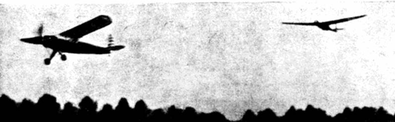
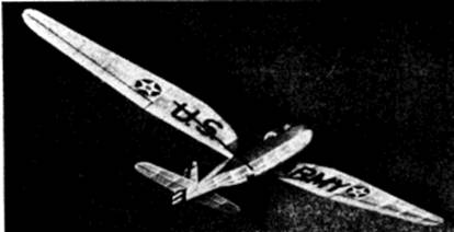
A Stinson 0‑49 tows an army glider, not full scale, just models. The glider is shown below
The Plan Page
[ Home ] [ Previous Plan Pages ]
[ Special Things ] [ Earl Stahl Plans ]
gt-hunter1@home.com
A Stinson 0‑49 tows an army glider, not
full scale, just models. The glider is shown below
SILENT MODEL WAR WINGS
Building a high
efficieney model of Uncle Sam's latest training glider
by
EARL STAHL
THE glider is writing a new and vitally important chapter of military aviation. By using aerial freight trains -- three to six heavily laden gliders towed by a huge multiengine plane -- it is possible to transport large numbers of troops and vast quantities of supplies and munitions to strategic positions. Recognizing the importance of motorless aircraft in modern warfare, United States armed forces are initiating a gigantic program of glider and glider pilot development.One of the most popular of several types of training gliders being used by Army, Navy and Marines is the Schweizer two-place sailplane. This is basically the same high performance plane that established records for altitude and distance in contests of recent years. Among many outstanding flights for this craft are a national distance record of 217 miles and an altitude hop of nearly 4 miles. The Schweizer is a semi-cantilever monoplane of all metal structure; fabric covering. The design is stressed for towing by airplane.
Of the several methods of launching training gliders, the airplane tow is most spectacular. In a manner similar to transporting troop -- carrying gliders, as many as three ships. using odd length towlines to prevent collisions, are carried aloft by a Vultee 0-49 observation plane. At the proper altitude the gliders cut free from the aerial locomotive and make a practice glide to earth.
To speed up the number of flights, possible in a given length of time, the Army in collaboration with All American Aviation, is experimenting with glider pickups by a plane already in flight. Using the same method employed by this successful airline in speeding airmail to small towns without airports, the plane dives to within a few feet of the ground and contacts the tow rope. A special mechanism absorbs the force of getting the glider in motion and a few seconds later glider and plane are climbing aloft for another practice descent. This method of air pickup has practical application for retrieving grounded troop and supply gliders, too.
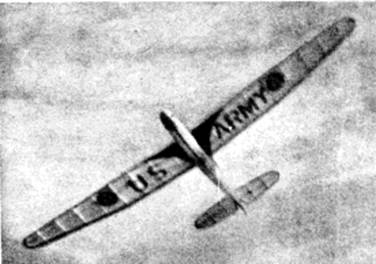 In full flight, responding to the slightest rising air current |
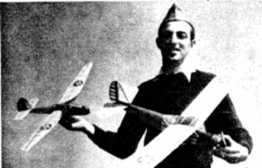 The author with the glider and tow plane after the flight shown above. |
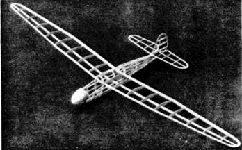 Though an efficient soarer, the uncovered frame shows simple construction |
 Structural details and decorations give a realistic effect. Note the belly landing gear |
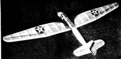 View from above shows simple efficient wing construction |
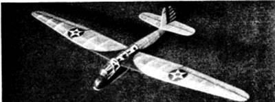 Finished scale model glider described in this article. |
Being somewhat different than the usual model, the flying scale Schweizer glider is most interesting. With towline launch it soars as well as any glider of similar size and with the aid of rising currents of air is capable of making flights of many minutes' duration. For added realism the author tried towing the sailplane with a rubber powered Vultee 0-49 (Formerly the Stinson 0‑49 for which plans were published in MODEL AIRPLANE NEWS, July 1941 issue) and results were very good. With the towplane slightly over powered, the glider can be carried quite high where the tow‑line drops free enabling the sailplane to cruise around on wings of the wind.
In construction the model is very simple; little balsa wood and no rubber is required, so it is very inexpensive. The flying scale Schweizer glider is constructed in the following manner:
CONSTRUCTION: Use of keel pieces cut from 1/16" sheet balsa simplifies fuselage construction and aids in making the structure more accurate. Trace the top, bottom and side outlines to obtain the correct shape of the keels, then with the aid of a sharp razor blade, cut them out. Bulkheads also are cut from 1/16" sheet balsa and two of each are required. Cut out the notches in the bulkheads as shown.
Pin the top and bottom keels to place over the side view to begin actual assembly of the fuselage. Cement half the bulkheads to their respective position, and then attach one of the side keels. When this structure has been finished, remove from the plan and add remaining bulkheads and side keel. Except for the four 1/16" sq. upper stringers, all others are 3/32" sq. stock. Once a stringer has been placed on one side always attach another on the corresponding position of the other side to keep from pulling the body out of line.
A solid balsa nose block is cemented to bulkhead A or if necessary, the nose can be built from laminated sheets of balsa. Cut and sand the nose piece so it fits neatly to the fuselage structure. Just behind bulkhead A small pieces of 1/32" sheet are fitted to form the cockpit front. Before leaving the fuselage structure it is best to attach the .040 music wire hooks that are needed to tow the model. Cement the hooks firmly to the keel and then reinforce adjacent areas with cement and scraps of balsa for added strength.
The sketch indicates how the rudder and stabilizer ribs are made. First construct a flat frame of both surfaces using 1/16" sheet balsa for outlines and 1/16" sq. stock for ribs and spars. When these flat frames are dry remove from the jig and cement soft 1/16" sq. strips to each side of each rib; these are later cut to a streamline shape.
Construction of the wing is next. It is made in two parts; it will be necessary to join the various sections of plan together so construction call be carried out atop it. Cut required number of ribs from 1/32" medium grade sheet. Sand ribs carefully and cut notches for the spar. Spar and leading edge pieces are cut from sheet stock as indicated and trailing edges are tapered strips of 1/8" x 3/8". Tips are cut from 3/32" sheet. Assemble parts right over the plan using pins to hold in place until cement has set. Finish the wing halves by cutting and sanding the tips and edges to conform to the airfoil's shape.
Before starting to cover the frames go over the whole structure with fine sandpaper to remove all flaws and roughness; this is absolutely necessary for or a neat job. The real Army Schweizers are colored blue and yellow, decorated with a color arrangement similar to the model pictured. Colored tissue is best for the covering job since it is both attractive and light in weight. Banana oil or thin dope is the adhesive used to stick the tissue to the frames. Cover the fuselage first using numerous small pieces, neatly lapped, to avoid unsightly wrinkles. It should be noted that the fuselage is not covered from section C to E above where the wing fits in. The nose, however, is covered with tissue. Cover wing and tail surfaces using an individual piece of tissue for each side of each unit; grain of the paper should run spanwise. Lightly spray the covering with water to tighten the tissue but do not apply any clear dope until the whole model is assembled.
The various parts are now assembled. Stabilizer and rudder are firmly cemented to position; check carefully for correct alignment. Slip the ends of the wings through the fuselage and cement them firmly being very careful to have them at the same angle of incidence and at the same time to have 1-1/4" dihedral at each tip. Scraps of sheet balsa can be cemented to the spar and leading and trailing edges at the center to strengthen the joint. Tissue fillets are doped to the openings at wing and tail surfaces to smooth out the appearance. The thin celluloid cockpit cover may scare some builders but it is really not too difficult to make. Patterns are given for the three front sections and the two rear pieces above the wing can be easily figured out as the work progresses. The patterns given are correct for the test ship but since each plane will vary a bit, they may need a bit of alteration. Start with the cover marked "back" and work forward from bulkhead C using cement to attach each. There is no frame under them but if the builder has any trouble, one can be made.
Once the scale effects are added, construction is completed. Wing struts were made from thin strips of bamboo for the original model, however hard balsa should be just as good. Cut away the tissue where struts join the plane so the junction will be as strong as possible. A dummy wheel is prepared and cemented to the fuselage bottom at the point shown. Color decorations can be painted on with regular colored dope or colored tissue can be used. Rudder stripes, U.S. ARMY under the wing and regulation stars are all made with colored tissue, however decals may be available to simplify the job. Thin strips of colored tissue doped to the celluloid effectively represent the window frames.
FLYING: To balance the model some additional weight will, in all probability, have to be added to the nose. By drilling a small hole in the balsa nose block, it will be possible to add lead or similar ballast until the ship rests on an even keel when held by the wing tips. Recheck the balance by hand launching from shoulder height; the glide should be long and smooth and in a nearly straight line. Correct balance or make any other adjustments necessary to get the desired smooth flight.
For launching by the regular towing method have an assistant hold the model. Regular thread with a 1/4" diameter wire loop on the end serves as the tow line; use only about 50 ft. at first. For windy days use the front hook on the model and when it is calm, use the rear one. Always tow the glider into the wind and never run faster than is necessary to get a smooth climb. As long as the line is being pulled the hook stays on; to release it, give the line some stack and it will fall free. For best results the glider should turn in 50 to 75 foot diameter circles. As flights improve longer towlines giving greater altitude can be used.
To carry the glider aloft by a rubber powered model, connect the two by about 15 feet of thread. The tow model should be adjusted for smooth rather straight flights. Attach the towline about midway up the rudder of the powered model. A third hook located about the center of the nose is needed to keep the glider from climbing too fast and thus nosing the first ship down. To get the ship off to a good start both should be launched at the same time with all of slack taken from the connecting thread. The loop on the glider will become disengaged as soon as there is slack in the line (usually at the top of the climb when the power is exhausted) so it is important that the power plane flies smoothly and that the glider is properly launched.
VICTORY
Scanned from December
1942
Model Airplane News
![]()
![]()
![]()
![]()
[ Home ] [ Previous Plan Pages ] [ Special
Things ] [ Earl Stahl Plans ]