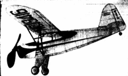
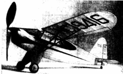
 The fuselage is strong, streamlined. |
 A large propeller provides long flights |
The Plan Page
[ Home ] [ Previous Plan Pages ]
[ Special Things ] [ Earl Stahl Plans ]
gt-hunter1@home.com
The fuselage is strong, streamlined. |
A large propeller provides long flights |
Build and Fly The Rearwin Speedster
At Last! The Perfect
Flying Scale Model‑Realistic in Appearance,
A Fine Flier and Easy to Build
By EARL STAHL
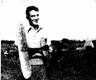
The author with twin speedsters ready for
a few flights
THE Rearwin Speedster is designed to answer the demand for a fast two‑place cabin monoplane combining exceptional speed with outstanding appearance. And the Speedster is indeed a masterpiece! Its perfected design combines speed and streamlining with comfort, safety and ease of flying.
Powered by a 125 horsepower Menasco engine, the Speedster zips along at a maximum speed of 150 m.p.h. The nonstop range, at 130 m.p.h. cruising speed, is 550 miles; while the landing speed is a comparatively slow 48 m.p.h. Economy of operation is an additional feature, for the Rearwin Speedster averages almost 17 miles per gallon of gas ‑ eloquent testimony of its efficiency.
Unlike most modern planes this one is a near‑perfect subject for a flying scale model. Its trim, slim fuselage with a high line of thrust and low center of lateral area lends itself admirably to model construction; the long fuselage aids flight stability and permits the use of a powerful motor of considerable length. Comparatively large tail surfaces combined with a rather small wing area further improve the possibility of fine flights. In short here is a fine scale model capable of making long stable flights despite the fact that it has been accurately reproduced.
The author has built three of these models and they have won awards not only in flying contests, but also when judged as scale models. Timed flights of one and one half minutes have been made; a fast climb which carries the plane high into the air combined with a long smooth glide making such flights possible. Why not build a Rearwin Speedster for that flying scale contest?
Following is the recommended procedure of construction:
Fuselage
Once the plans are properly joined together, construction can be started. A rectangular frame is the backbone of the fuselage. Two sides are built from medium grade 3/32" square balsa, one atop the other to insure identity. When dry, the sides are inverted over the top view; pinned into position. Then cement the 3/32" square crosspieces into place, being careful the whole structure is lined up properly. Cut the bulkheads, halves of which are shown on the plan, from 1/16" balsa, and now if the basic frame is dry it should be removed from the work board and the bulkheads cemented into place. The wing center section, consisting of two wing ribs joined together, is built directly atop the plan and then it too is cemented into place. Doing this will insure the correct placement of the wing in final assembly. Note that most of the bulkheads lack notches for stringers, and when this is the case the 1/16" square stringers are glued directly atop the bulkhead. This method helps eliminate wavy stringers and aids in making a more perfect covering job. The stringers on the sides of the body are glued directly to the underframe.
The whole nose is covered with 1/32" soft sheet balsa. While this is not difficult it does require careful work. Start at the top, using three inch wide stock if possible, and cement the covering to the entire adjacent frame. Rubber bands wrapped about the sheet and plenty of pins will aid in holding the covering in position until dry. Additional wedge‑shaped sheets with the grain running as indicated will be needed when the bottom is reached. Make neat joints where the individual sheets meet. A nose block is carved from a 1/2" thick block. Accurately cut the nose plug hole and then cement the block into position for final finishing.
Landing gear struts are cut from very hard 3/16" sheet balsa. Cut and sand them to a streamlined shape and bevel the tops so they will fit neatly when joined within the fuselage. The slot at the top fits to bulkhead number 8. If the tread is 4‑3/8" the landing struts should be securely cemented into position‑use plenty of glue and you will find this undercarriage is very strong. Wheels are laminated sheets of 1/8" balsa shaped as shown on the plan. Don't place them in position, however, until the fuselage is covered. Since wheel‑pants are listed as optional equipment in literature received from the factory, we have eliminated them on our models, for they would probably detract from the flying ability.
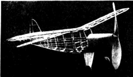 The uncovered frame shows fine construction. |
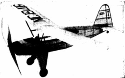
 It is very realistic with decorations |
Wing
Because of limited space only one‑half of the wing could be reproduced on the plan; so make a full‑sized layout on a large sheet of paper and work can be done directly on it. It should be noted here that the airfoil used on our model is not scale‑those desiring an exact scale model should use an M‑6 wing section. Taper and sand the trailing edges before pinning them into position over the plan. Wing ribs cut from medium grade 1/16" sheet should be pinned into their respective positions and the hard 1/16" square spars and 1/8" square leading edges added. Tilt the inner ribs of each panel slightly to insure a good fit when the dihedral is added. The small tip ribs are formed from larger ones by the "cut and try" method after the wing tips have been cemented into place. Once the leading edges and tips are trimmed and sanded to their proper shapes the wing framework is completed.
Tail Surfaces
The tail surface construction is quite simple. Both rudder and stabilizer are constructed similarly; the plan being nearly self‑explanatory. Make the stabilizer in one piece. The streamlined rib shape is made by gluing 3/64” x 1/16” strips to both sides of the underframe and later cutting them to shape. This manner of construction is strong, yet light. Carefully trim and sand the entire unit so a smooth covering job can be made.
Propeller
The propeller is carved from a hard block of balsa 1" x 1‑1/2" x 9‑1/2". Cut the blank as shown but without the spinner. A right‑hand propeller should be used; the back face of each blade having about 3/32" undercamber. Cut the blades to a nice smooth shape‑take your time and do a good job. The spinner is made by gluing small blocks to the sides and when dry they are given the desired shape. Several coats of light dope will give a nice finish if fine sandpaper is used between coats. The freewheel device is the popular dog‑tooth type; make it from 1/64" sheet brass. Protect the back of the prop with a brass washer, too.
Make the nose plug to fit the hole in the nose block. The back is made from hard balsa, while the front piece is a disk of 1/32" birch plywood. Fix the line of thrust by gluing washers to either end of the nose plug. .040 music wire is used for a propeller shaft.
Covering
Being a scale model it is necessary that the covering be near perfect. With this in mind carefully sandpaper every bit of the structure to remove any roughness. If any fuselage bulkheads are apt to touch the covering, use a piece of sandpaper wrapped about a pencil to make certain only those members running fore and aft touch the paper. The plane shown in the photos is colored orange with black trim; for it is best to select a light base color and dark trim if paper rather than paint is to be used for decorations. Cover the entire plane with the light‑colored tissue, the balsa covered nose and lauding gear included. Numerous small pieces of paper on compound curves will help avoid wrinkles. Except on the wing's undersurface, the banana oil adhesive should be applied only to the extremities of the part to be covered. All covered parts should be lightly watersprayed to tighten the tissue, but avoid warping of the flying surfaces. Wing license numbers, fuselage stripes and trim, as well as control surface outlines, should be applied at this time. Once the numbers, stripes, etc., have been cut out, they should be placed in position and light dope applied with a brush over them rather than try to place them properly after the adhesive has been applied. Such marking as "Rearwin Speedster" and the license numbers on the rudder are made with pen and India ink.
Assembly of the various parts completes the construction. The windshield pattern found on the plans may need slight altering since most models will vary slightly. The windshield is cut from thin celluloid, and it is cemented into position. .034 wire axles are fitted to the wheels. Neatly bind the axles to the landing struts and cover the thread wrapping with tissue. The stabilizer is slipped into position and glued firmly. Offset the front of the rudder about 1/32" so the model will glide to the right. Carefully line up the tail surfaces making the stabilizer parallel to the workbench and the rudder perpendicular to it. Block up each wing tip so there will be 1‑1/4" dihedral; making certain the angle of incidence of each wing is the same, and then glue all joints firmly. Small tissue fillets at the junction of fuselage and tail surfaces will make the model more attractive. Apply two coats of light dope to the whole plane at this time‑not before. Dope in a dry room to avoid blushes. Streamlined wing struts made of 1/16" x 3/16" hard balsa strips and colored dope are placed in the position shown; again using the "cut and try" method for an exact fit. Cut away the tissue where the struts join the wing and body. Additional details such as tail wheel, etc., are added at this time. Once the propeller is color‑doped to a high luster the construction is finished.
Flying
Ten to twelve strands of 1/8" brown rubber, 17 inches long, should be used to power this model. Protect the prop shaft with adhesive tape so the wire will not cut the rubber. A 1/16" round bamboo pin in the rear holds the rubber motor and provides a place to hold while winding. The original models all climbed very steeply in a large left circle and they glided to the right. If the plans are closely followed the model should balance and fly with very little adjustment. Add weight to the nose or tail as needed to make the Speedster glide well, and then adjust the thrust line to correct the power flight. Slight down‑thrust will eliminate a tendency to stall, while right or left thrust will make the plane turn as desired. Use a mechanical winder for long flights ‑ stretch the rubber motor about 2‑1/2 times normal length and store in about 800 winds. A little effort and caution will reward you with a fine plane which is truly attractive and yet a swell flyer.
Scanned From January, 1940
Model Airplane News
![]()
![]()
![]()
![]()
[ Home ] [ Previous Plan Pages ] [ Special
Things ] [ Earl Stahl Plans ]