
BY EARL STAHL
A "natural," either in the air or on, the ground,
your PT19 model will be a standout.
A real PT‑19, breezing along at its 125 m.p.h. cruising
speed,
is the last word in primary trainers.
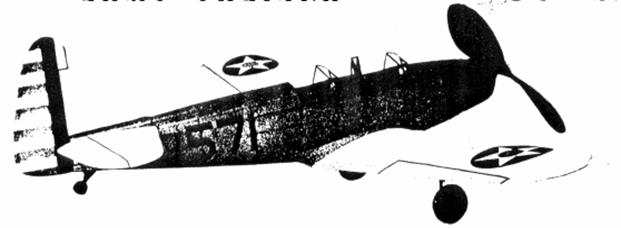
Below - Completed model.
The Plan Page
[ Home ] [ Previous Plan Pages ]
[ Special Things ] [ Earl Stahl Plans ]
gt-hunter1@home.com
BY EARL STAHL
A "natural," either in the air or on, the ground,
your PT19 model will be a standout.
A real PT‑19, breezing along at its 125 m.p.h. cruising
speed,
is the last word in primary trainers.
Below - Completed model.
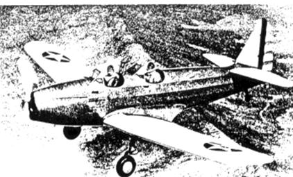
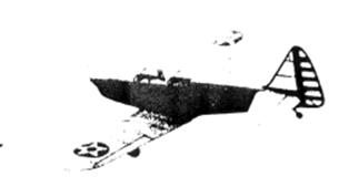
DESIGNED to meet the rigid requirements for training planes of the United States army air corps, the Fairchild PT‑19 is of a design similar to the majority of combat planes, yet it possesses the flight and strength characteristics required of training aircraft.
This two‑place. low‑wing monoplane is powered by a Ranger engine of 175 h.p. which gives a speed of 135 m.p.h. Construction is conventional, wood, metal and fabric being used; the cantilever wing is plywood covered. A high degree of visibility, an important factor in all training planes, is achieved by the use of the inverted, in‑line engine and the open cockpits.
From the modeler's point of view the PT‑19 affords a fine subject for a flying scale model. The test model was built to exact scale except for a slight modification of the stabilizer area and, of course, the enlarged propeller; it is capable of making flights of about one minute. Because of the plane's simple, efficient design, it is not difficult to construct an authentic, sturdy model from the full‑size plans, which are presented here.
CONSTRUCTION
The fuselage under‑frame is constructed first. Work directly over the plan and make two side frames. The longerons are 3/32" square, while the uprights are 1/16 x 3/32" balsa. When dry, the side frames are inverted over the top view of the fuselage and the cross pieces are cemented in place. Check frequently to assure proper alignment.
Formers are cut from soft grade 1/16" sheet balsa. It will be noticed that a number of the formers do not have notches for the stringers; where this is true, the stringers are to be attached directly to the sides, as shown. Cement the formers to their respective positions and then add the 1/16" square stringers. On the bottom of the fuselage between Sections 3‑B and 6‑B the stringers are omitted, since the wing is later placed in the recess. Stringers which run back the sides are cemented directly to the under‑frame.
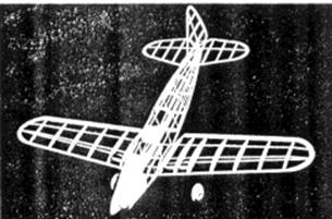
Construction, ready‑to‑fly, and flight!
To represent effectively the metal engine cowling of the real Fairchild, the nose forward of Section 2 should be "filled in" with pieces of 1/16" sheet. Accurately cut the individual pieces so they will fit neatly within the space between the stringers and formers. The nose block is cut from a medium‑grade piece; cut out the square hole, as shown, for the rubber motor to pass through. Cement the roughly cut block to the nose and then sandpaper the whole nose to a smooth, attractive shape. If desired, the nose can be covered with thin sheet balsa instead of the suggested method.
The top of the fuselage from 3‑T to 6‑T is covered with soft sheet. Space limitations prevented making a complete pattern of this part but the cockpit shape is indicated. A piece 1/32 x 2 x 4‑9/16" is required; check the plans for the exact position of the cockpits. Cement the covering in place, using pins to hold it fast until dry. Finish the section between 2‑T and 3‑T by "filling in" with sheet balsa as before.
It is necessary for the wing to be of sturdy construction since the landing gear is attached to it. Ribs are cut from 1/32" sheet with the exception of W‑4 which is 1/16" thick; two of each are required. A full‑size left wing plan must be made. The various parts are assembled directly over the plans. Sizes of the various spars, et cetera, are noted on the plan. The 1/16 x 1/4" hard balsa spar to which the landing struts are attached is not placed until the dihedral is added. Scale dihedral of 1‑7/8" proved satisfactory on the original model, but to those not interested in exact scale we recommend an increase of about 1/4" in each wing for an added measure of stability. The wings must be joined together accurately and solidly. Attach the 1/4" deep spar and reinforce the junction necessitated by the dihedral. Trim and sandpaper the leading and trailing edges as well as the tips.
Any excess weight in the rear of the model must be balanced by additional weight in the nose, so exercise care to prevent any unnecessary weight in making the stabilizer and rudder. Both are constructed in a similar manner; the outlines are cut from 1/16" sheet and the spars and ribs are 1/16" square medium stock. Light strips are cemented to both sides of the ribs and when dry they are cut and sanded to the streamline shape indicated on the plan. Surfaces constructed in this manner are light yet they will not warp readily.
The landing‑gear struts are fashioned from .040 music wire. The wire is bent in such a manner as to join the spar provided for that purpose and Rib No. 3. Attach the struts in place with thread and plenty of cement; use a needle and sew right through the rib and about the wire. Be sure to make a right and left strut. The balsa and rubber tubing covers are added after the wing is covered.
Wheels are made from laminated disks of balsa, or they may be purchased. Bearings should be cemented to the sides so they will revolve accurately and smoothly.
A neat, attractive covering is necessary for any fine flying scale model. The frame must first be prepared for the covering by lightly but thoroughly sanding every part to remove all flaws and roughness. Blue and yellow colored tissue is used. Cover the fuselage first using the blue tissue. Thin dope or banana oil is used as adhesive to stick the tissue to the frames. Grain of the paper should run from the nose to the tail. Numerous small pieces of tissue must be used to prevent wrinkles; individual pieces should be lapped neatly. The nose and other wood parts should be covered with tissue, too. The wings and tail surfaces are covered with the yellow tissue; the grain runs spanwise. Attach only the extremities of the area being covered. Tips, et cetera. require separate pieces. The parts are lightly sprayed with water to tighten the tissue, but they are not doped until the model is assembled.
The various parts should now be assembled. Cement the wing in place; if the structure has been reproduced accurately the angle of incidence will automatically be correct. Finish the under section from wing to fuselage with pieces of 1/16" square. Wing root pieces W‑R are cut from 1/16" sheet and attached between the wing and fuselage. Fillet pieces to be cut from 1/64" sheet are shown on the plan. The pattern indicates the shape of the fillets on the original model, but since more miniatures will vary a little, paper patterns should be made to fit your model exactly before the sheet balsa ones are cut. After the fillets are cemented in position, they are covered with blue tissue, as is the uncovered portion under the wing. It will be necessary to cut the rear of the fuselage temporarily to admit the stabilizer, which is attached at the exact angle indicated. Offset the rudder a bit to counteract torque. Tissue fillets are placed between the stabilizer and rudder. Any wrinkles in the covering should be moistened with water and permitted to dry before the entire model is given a coat of clear dope. Dope should be applied in a dry room to minimize tile chance of "blushing."
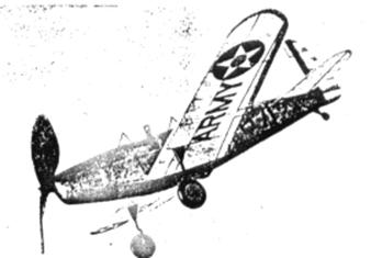
Numerous details can be added to improve the model's appearance without harming the flight ability. Streamline covers at the top of the landing gear struts are made from pieces of balsa, while the lower part of the strut is covered with rubber tubing of the correct size. Washers soldered to the ends of the axles will hold the wheels in place. The stars, rudder stripes, U. S. ARMY," et cetera, are made from colored tissue and the effort required in making them will be amply repaid by the snappy appearance they add to the model. Control surfaces are outlined by thin strips of black tissue. The pylon between the cockpits ‑‑ it protects the pilots in the event of a turn‑over ‑- can be made from thin pieces of bamboo. Celluloid windshields, the tail wheel and other details should be added.
For best flight performance any flying model must have all efficient propeller. Select a hard block 7/8 x 1‑3/8 x 7-1/2" and cut out the blank as shown. Carve a right‑hand prop with a bit of undercamber in each blade. The spinner is made in two pieces and glued to the sides of the prop. Cement a washer to the back so it will revolve smoothly. A freewheel device of some sort should be used to help improve the glide. Sand the propeller and color‑dope to a nice finish.
The removable nose plug is shown. A disk of 1/32" plywood forms the front while the back is laminations of balsa. Fix the thrust line by cementing washers to the front and back of the plug.
For the prop shaft .034 music wire is used. A loop to which the winder can be attached should be bent on the front of the shaft. Place several washers between the propeller and nose plug.
Eight strands (four loops) of 1/8" brown rubber are used to power our trainer. Hook the rubber to the prop shaft and with the aid of a weighted string; drop the other end through the fuselage. A bamboo pin holds the motor in the rear.
FLYING
To prevent damage to the model at this crucial stage, test flights should be made over deep grass. The descent from a hand glide should be flat and smooth, a small corrective weight may be required to obtain the desired results. Once the glide is good, all further adjustments are made at the nose plug. Right or left thrust will control the amount of circle, and a bit of downthrust will correct a tendency to mush or stall.
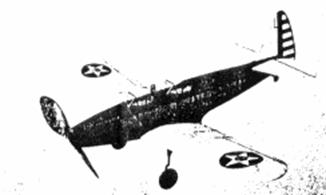
The author's PT‑19 has been flown many times and proved to be an excellent performer. When winder wound it climbs in large left circles until the power is exhausted and then it descends in easy right spirals. It is tough, too, having emerged from encounters with trees and other model catchers with only minor tears in the covering.
Earl Stahl's fine PT‑I9 is the result of careful work. Take
your time.
Scanned from December 1940
Air Trails
![]()
![]()
![]()
![]()
[ Home ] [ Previous Plan Pages ] [ Special
Things ] [ Earl Stahl Plans ]