The Plan Page
[ Home ] [ Previous Plan Pages ]
[ Special Things ] [ Earl Stahl Plans ]
gt-hunter1@home.com
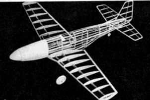
The proof of
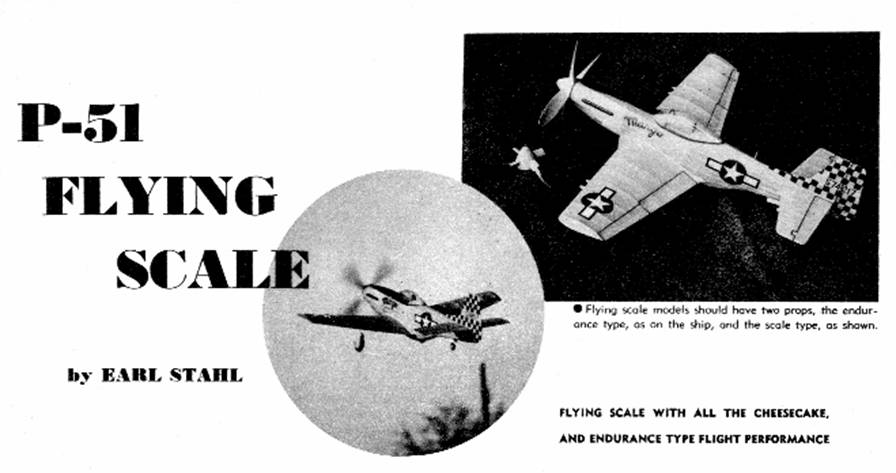
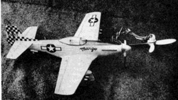
the pudding is in the eating. Super‑details,
such as the rockets, bombs, and droppable gas tanks,
have not detracted from its flying performance.
POSSESSORS of some of the most brilliant fighting records of the war, the P‑51 Mustangs blazed a trail of destructive glory through enemy skies. Particular favorites of Allied airmen, they were feared and respected by the Germans and Japanese.
Attaining greatest acclaim as long‑range fighters, squadrons of Mustangs became familiar sights over Berlin and Tokyo as well as other remote targets. Used in great numbers, first as escorts for the heavy bombers, when they were making deep penetrations into enemy territory, these aerial terrors were later used tactically in offenses against ground installations, such as supply dumps and transportation facilities. When flying protection for the bombers, range was increased by carrying fuel in external tanks beneath the wings, and the normal armament consisted of six .50‑caliber machine guns. For sweeps against ground targets, rockets and bombs were mounted beneath the wings. All in all, the ships packed a deadly wallop regardless of the mission for which they were outfitted.
Before the United States entry into the war, the Mustang was conceived by North American Aviation in response to Britain's cry for a high‑performance fighter. The plane that resulted proved so satisfactory that it was adopted by our Army as one of our top fighters. The original P‑51 was powered by an Allison engine for fighting at low altitudes, but it was not until the Packard‑built Roll‑Royce engine was used that the high‑altitude, long‑range performance of the present‑day ship was attained. Actually, the Mustangs that saw service in the closing days of the war were a far cry from the original. Aside from the changes in fighting equipment that developed through experience and the changing trends of the war, lines were altered by the new engine, the bubble canopy and the dorsal fin‑only the high speed NACA laminar‑flow wing and the horizontal tail appear unchanged.
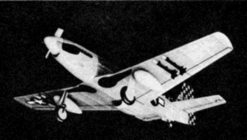
Our model is of the latest Mustang, and while emphasis has been placed on flying ability, it is accurately reproduced in line, thus making an unusually attractive display project. Perhaps a glance at the drawings and photos may give the impression that building is difficult, but the opposite is true, for no complicated structures or methods are employed and even the catchy‑looking bubble canopy is made quite easily.
Experience has demonstrated that low‑wing models can be made to fly well and the P‑51 Mustang is no exception. Aerodynamic proportions have been worked out carefully and so if the structural weight is not allowed to become excessive, long, stable flights can be expected.
Before starting to build, study the drawings and text to get a complete mental picture of each problem. Proceed then with care and the reward will be a neat‑appearing, fine‑flying miniature.
In selecting materials for your model, obtain the best possible. Balsa wood, which comprises most of the structure, should be light, firm stock. Regular colorless model airplane cement is used to join the members.
To build a full‑size model, it will be necessary to enlarge the drawings to twice the printed size. This will enable construction to be done directly atop the plans, which is the best and easiest way. However, a model of the size shown may be made without altering the prints; unfortunately, though, small models do not fly as well as their bigger brothers, so we must recommend the latter.
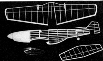
The fuselage is usually a good item to start with, so let's get under way. The type of construction used in this ship calls for sheet balsa formers mounted on four sheet balsa keels; stringers to give the proper shape are thin balsa strips. This method of building is most practical since it is both easy and strong. First cut the four keels and numerous formers (note that two of each are required) from 1/16" thick medium grade balsa. To assemble these parts, pin the top and bottom keels right over the plan, then cement half the formers and one side keel to place. Next lift this frame from the plan and add the remaining formers and keel. Stringers are 1/16" sq. stock and are placed two at a time on opposite sides to keep from disaligning the structure. Note that in some cases it will be necessary to cut the stringer notches in the formers as work proceeds; this is done in order to assure perfect alignment of these members and it does not make the task more difficult. It will be noticed that at the point where the wing fits in, curved 3/32" sheet balsa formers are used to make the fuselage sides fit to the curvature of the wings' top surface.
A few more items and the fuselage structure can be laid aside. For realism and strength, the nose is filled in between stringers and formers with rectangles of soft 3/32" or 1/8" balsa. This takes extra time and patience but it is worth it in the improved appearance and added strength. The nose block is made from crossed‑grain 1/8" balsa laminations as is the belly radiator front. Be sure to cut out the square hole for the nose plug before ‑cementing the block to the front former. To complete the fuselage, place the sheet balsa pieces for the cockpit and attach 1/8" thick blocks in the rear of the fuselage to cradle the bamboo pin that holds the rubber motor.
The wing and tail surface construction is so simple that little need be said. Note the sizes of the materials indicated on the plan and cut the parts from sheet balsa. For the wing, the leading edge and spar are tapered so they must be cut from sheet balsa too. Assemble the wing in two halves over full‑size drawings and then join the parts by securely splicing the spars and leading edge; tips should be raised to the amount of dihedral shown. The tail surfaces are deep structures with ribs made wider and streamlined by overlaying 1/16" sq. strips on each side of each rib and then trimming them to shape.
A very realistic and practical landing gear is employed. Bend the single struts (left and right) from .040 music wire. Then bind and sew them to the wing structure, using light, strong thread and finally cement to secure them. Wheels on the original were made from laminations of 1/8" sheet balsa but ones of correct diameter may be stocked by your neighborhood supply house. Attach washers or bearings of some sort to each side of each wheel to make them turn freely and accurately. The tail wheel on the original did not turn but served as a most realistic skid. It is a disk of balsa mounted on rounded bamboo which is in turn forced into the bottom keel and cemented fast.
Since the real plane has a four‑blade propeller, we used a four-blader of flying proportions on the model. Actually, we believe a two‑blade one would be just as satisfactory, so far as flights are concerned; the choice is left to the builder. Cut the blanks from very hard balsa, notch them as shown, and then cement them securely at 90 degrees to each blade. Carve a right‑hand revolving prop, rounding and balancing the blades carefully. The spinner is soft balsa, shaped and then notched to fit over the blades. It is so large that a free‑wheel gadget that will permit the prop to revolve freely once the rubber motor is exhausted can be hidden within it. Before the spinner is attached, install the .040 music wire shaft. The remaining part of the prop unit, the nose plug, is made from a 1/32" plywood disk backed by a cube of balsa and slipped on the shaft, but first be sure to fix the line of thrust by cementing washers or other bearings to the front and back.
Before parts may be assembled, they must be covered. The covering operation is probably the most important of all for it can largely make or ruin the whole project, depending on whether or not a good job has been done. With this in mind, carefully sand all the frames until they are flawless. In this connection the author likes to sand the fuselage formers slightly scalloped so the stringers only will touch the paper; this makes for a much better job. Use banana oil or very light dope to stick the paper to the frames, and where compound curves exist, employ many small sections of the tissue, neatly lapped to avoid unsightly wrinkles. This takes more time, of course, but the results are worth it. A fine mist of water sprayed on the covering will tighten it but do not apply any dope until the whole model is assembled.
The final assembly is easy. If the parts have been made with care, wing and stabilizer will slip right into place at the proper aerodynamic angles as this was predetermined; align them carefully before cementing fast. To make the wing fillet make the sheet balsa parts shown and fit them individually to your model. Cover the fillet and bottom opening with matching tissue. Cement the vertical tail fast at a slight offset to the left (leading edge) for a right turn to help overcome torque. Now neatly fit a tissue fillet between the tail surfaces. At this time, one or two coats of clear dope may be applied to the whole model to further tighten and strengthen the tissue. On our original models we always mix a small quantity of dope of the same color as the tissue with the clear to better the appearance of the finished plane; this makes a distinct improvement and adds little or no weight.
From this point on, everything that is added to the model, provided, of course, that it is skillfully done, will improve the appearance. To make the landing gear look realistic follow this procedure: Slip 1/8" diameter rubber tubing on the struts and paint them aluminum. Color the wheels and tires and fix them to the axles with a drop of solder. Make the wheel well covers from 1/32" sheet balsa and cover them with tissue to match the wings; these are cemented to the struts but not the wing so they can spring freely to absorb landing shocks. To simulate the wheel wells, cut black tissue to the appropriate shape and dope to the covering. The tail wheel should be painted and 1/32" balsa retraction covers installed.
Probably the biggest item is the making of the bubble canopy. It is really not hard and we went about it in this manner: A balsa canopy was first carved. Then a piece of soft plastic was heated in boiling water until it became pliable. (Vinylite, Lumerith, or even celluloid 1/32" in thickness or less, can be used.) Then, using every hand that was available, we stretched it down over the form. (A person with five or six hands could do it alone!) Work very rapidly as the plastic resets quickly, but in the event that results are unsatisfactory, simply reheat and try again. Incidentally, structural details of the canopy are represented by thin strips of black tissue.
Few details remain. Control surface outlines are represented by fine strips of black tissue which are doped to the wing and tail. Exhaust ports, antenna, scale propeller, bombs, rockets gas tanks, or what have you are made from odds and ends but go a long way to enhance the model's appearance.
To prepare the little ship for flight a rubber motor must be installed. Use 12 strands of 1/8" flat, brown rubber for power. Hook the end of the loop to the prop shaft and then drop the other end, which has the strands tied together by a loop of thread, through the fuselage and then slip the bamboo retainer pin in place to secure them. Your Mustang is now ready to try her wings.
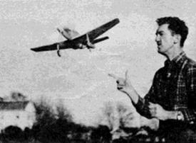
Wait for a calm day and go to a grassy field to make the test hops. First glide the model to check the center of gravity; if it stalls, add a small amount of weight within the nose and, should it dive, put a small weight near the tail. Once it glides okay, try a few power turns, gradually increasing the amount as flights improve. Adjust the power flight attitudes at the nose plug by off‑setting the thrust line. Tilting the thrust line down (small block of wood at the top of the plug) will iron out a tendency to stall while right or left thrust will control the amount and rate of turn. All thrust adjustments are to be made with the assumption that the glider remains unchanged and good. To get flights of the longest possible duration once adjustments are okay, devise
a means of hooking the rubber motor to a mechanical winder. (On the original we hook right onto the loop at the back of the shaft and spin the prop about the winder while cranking it up.) Stretch the rubber two or three times normal length before starting to store up power and in this way many more turns can safely be wound in. Get out in the wide open spaces to fly her once she is all in trim, for you don't want the neighbors calling the nearest airport to report a P‑51 Mustang buzzing their house.
Scanned from June, 1946
Air Trails Pictorial
![]()
![]()
[ Home ] [ Previous Plan Pages ] [ Special
Things ] [ Earl Stahl Plans ]