The Plan Page
[ Home ] [ Previous Plan Pages ]
[ Special Things ] [ Earl Stahl Plans ]
gt-hunter1@home.com
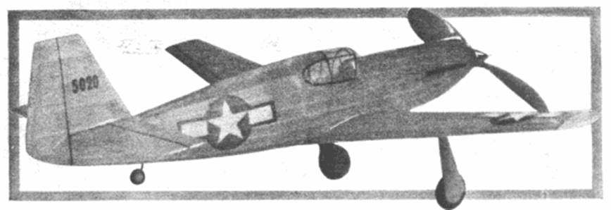
MODEL MUSTANG
by EARL STAHL
THE North American P‑51B Mustang featured on our cover this month is of ideal layout and its favorable design makes it highly satisfactory for a scale model with good flying qualities.
The plan is for a balsawood model, but if the builder is unable to obtain sufficient balsa for the whole job, pine or similar material may be substituted without impairing the model's flying ability.
Conventional construction methods are followed. Be sure to do the work neatly and accurately, and exercise care to cement all joints firmly. Where pine or other such wood is substituted, the thickness of the part should be reduced since the material is stronger.
CONSTRUCT1ON‑Full size plans are presented, and with the exception of one wing and stabilizer half, no redrawing will be necessary; work right over the plan to simplify and speed construction. Make the wing first. It is built in two halves which are later joined. Ribs Nos.1, 2, 3 are 1/16" thick balsa while the others are 1/32". Cut and sand the ribs carefully to exact shape. The leading edge and spar are cut from sheet, balsa and are tapered as indicated. Assemble the parts over the plans using pins to hold them in place; cement the joints solidly. Trim the leading and trailing edges as well as, the 1/8" sheet tips roughly to shape; then sand the whole structure.
Use of the keel and bulkhead method simplifies the fuselage construction. Cut two of each bulkhead from 1/16" sheet. To assemble, pin the top and bottom keel in place on the side view and attach the half bulkheads. Add the side keel, and when this structure is dry remove from the plan and add the remaining bulkheads and keel. Now place the 1/16" sq. stringers starting nearest the side keel; be careful to keep from disaligning the frame by adding a stringer to each side at the same time. Cut the notches as required, and be careful to align them perfectly.
At the recess for the wing, curved pieces of 3/32" sheet are required. They are similar to the center keel in shape and they should fit the curvature of the wing neatly. Two pieces of 1/4" sheet cemented together form the nose block; roughly cut it to shape before cementing to bulkhead No. 1. Note that the center of the nose block is cut out to receive the nose plug. In the rear where the rubber holding bamboo pin is mounted, attach hard sheet retainers. For the curved windows behind the pilot's cockpit a frame is required; it is carved from several pieces of sheet balsa.
On the real P‑51 a radiator is mounted under the belly. This was eliminated on the original model in the interest of better flights. Those desiring maximum scale will want it, however, therefore crossections are shown. It may be of built‑up construction or hollowed out from a solid block of balsa. It is best to leave the radiator off until the wing has been covered assembled to the fuselage.
Rib construction of the stabilizer and rudder is shown in the sketch. Make flat frames of each (the stabilizer is built in one piece) using 1/16" thick stock for the outlines and 1/16" sq. for spars and ribs. When these 1/16" frames are dry, remove from the jig and attach 1/16" sq. strips to both sides of each rib. These are later cut to the streamline shape shown. Trim the leading and trailing edges to conform to the rib shape.
A simple but highly practical landing gear is featured. Using .040 music wire, bend the front view as shown by the
full size plan, then bend the top of the wire so that it joins the rib and spar as shown. Be make a right and left leg. Using a needle and thread, bind the wire to the structure and sew right through the rib. Cement the thread and adjacent areas thoroughly to strengthen the structure. Wheels may be purchased but it is a simple task to make them from laminated sheet balsa. Fix bearings to both sides of each wheel so they will revolve smoothly and accurately. Other details of the landing gear will be completed later.
A hard balsa or white pine propeller is recommended. Cut the blank to the shape and dimensions shown. It is best to make the spinner separate. Drill the tiny prop shaft hole first, then cut away the back surface of the blank until the camber is as desired. Now cut away front until the blades are of the desired thickness. Round the tips and reduce the depth of the hub as indicated. Blades are brought into balance by sanding. The spinner is soft balsa and may be made in several pieces to fit, or as one unit and notched to fit over the hub.
The nose plug is detailed on the plan. It consists of a 1/32" plywood disk backed by several laminations of 1/8" sheet. Drill the hole through it slightly to the right so there will be a few degrees of right thrust. Washers are cemented to both the front and back to fix the line of thrust. Music wire .040 thick is used for the propeller shaft. For best flights a freewheeling gadget that will permit the propeller to spin freely in the glide is recommended.
Before the frames are covered they must be sanded to perfection or else a good job can not be made. Colored tissue is suggested and it may be attached to the frames by banana oil or light dope. Use a separate piece of tissue both sides of each wing and stabilizer half. For the fuselage numerous small pieces neatly lapped will be required to avoid unsightly wrinkles. Water spray the covering lightly to tighten it Fix the flying surfaces, in a level position while drying so they will not warp but do not apply any dope until later.
Assembly of the parts must be done with accuracy. First fit the wing within the recess and cement it fast. Align the stabilizer with the wing and then finish the area from fuselage to it with scraps of balsa and tissue. Attach the rudder perpendicular to the stabilizer, off‑setting the front of it about 1/32" for a right turn. Now one or two coats of light dope can be brushed on the covering to tighten it.
Addition of the various details completes the construction. Thin celluloid is used for the cockpit enclosure; it may be obtained from cleaned photo film. Structural details of the enclosure are represented by thin strips of black tissue doped to the celluloid. Finish the landing gear next; rubber or cloth insulating tubing slipped from electric cords, etc., is used to cover the wire landing gear legs. Wheels should be painted before they are held to the axles by drops of solder. The cover that closes the recess once the landing gear is retracted on the real plane is represented; it is made from 1/32" sheet. Attach it in such a manner that the strut is free to spring and thus absorb shock. If a radiator is used it should be attached now. Details such as exhausts, air scoop, tail wheel, etc., are made from scraps and they go a long way to enhance the appearance of the model. Naturally all exposed wood parts should be painted.
FLYING‑Depending on the finished weight of the model 10‑12 strands of 1/8” flat rubber will be needed for power. Before placing the motor within the fuselage, lubricate it. The rubber strands are held in the rear by a bamboo dowel. The plane is now ready for its test flight
Careful testing is required to get the maximum performance from any model. Roughly adjust the center of gravity of the little ship first by adding weight to the nose or tail to bring it into balance when held at the wing spar. Then make any further weight adjustment by gliding from shoulder‑height. If it stalls, add weight to the nose. If it dives, remove weight or add a bit to the tail.
First power flights should be made with just a few turns, and as the performance improves and confidence is gained, increase the power. Tilting the thrust line down will eliminate a tendency to stall under power, while right or left thrust will control the amount of circle. Once flights are satisfactory, use a mechanical winder to store up maximum power. The original model flew best when it was adjusted for a large left circle under power and a sweeping curve to the right in the glide.
VICTORY
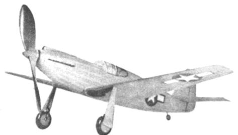
This view of the Model Mustang shows clearly its simple structure and clean lines.
Scanned from May,1944
Model Airplane News
![]()
![]()
![]()
![]()
[ Home ] [ Previous Plan Pages ] [ Special
Things ] [ Earl Stahl Plans ]