The Plan Page
[ Home ] [ Previous Plan Pages ]
[ Special Things ] [ Earl Stahl Plans ]
gt-hunter1@home.com
PILOT THIS
MODEL HAWK P‑40D
Complete instructions for building the
latest
model of Uncle Sam's most famous fighter
by
EARL STAHL
For this month as a flying scale feature offer a model of the famous Curtiss "Hawk" P‑40D, the fighter that is carrying the war to the Axis oil the far flung battle fronts of the world.
The new Curtiss "Hawk" P‑40D and its counterpart the British "Kittyhawk" are advanced versions of the well-known P‑40 of the Army Air Forces and the "Tomahawk" of the Royal Air Force. Speedier, with improved all-around performance, greatly increased firing power and more protective armor, they are being produced in vast, ever increasing numbers.
Performance figures are restricted, but it is known that the maximum speed of the Allison powered version compares with the "Spitfire's" 367 m.p.h. A similar but newer model, the P-40F, with an American made Rolls Royce "Merlin" engine is even faster. Reports from the Middle East inform us that Germany's latest 380 M.P.H. Messerschmitt Me 109F's are speedier but the more maneuverable heavily armed R.A.F. "Kittyhawks" are considered superior. Five to one in favor of the "home team" is the African average to date! In the Pacific theater these potent fighters piloted by gallant American airmen have repeatedly demonstrated their superiority against fighters and bombers of the "Setting Sun."
Every flying scale builder will want for his fleet a replica of this famous fighter which has the same fine characteristics as the real ship. Its appearance is unequalled; the construction easy and in performance compares favorably with any similar ship - a picture on display or in flight. Standard construction methods are used throughout, nevertheless, it is advisable to study the plans and instructions thoroughly, before building.
CONSTRUCTION - Use of keels, cut from sheet balsa, simplifies assembly of the fuselage and aids in making the structure more accurate. Trace the top, bottom and two side keels on 1/16" sheet balsa and then with a sharp razor blade cut them out. The section between D and E has no support at the top (cockpit opening) but a curved piece conforming to the wing upper surface is placed at the bottom as indicated. Bulkheads also are cut from 1/16" sheet and two of each are required. Notice that not all bulkheads have notches for stringers cut out the notches shown and mark the positions of others, which are cut later as needed.
Pin the keel pieces over the fuselage plan to begin actual assembly. Cement half of the bulkheads to their respective positions, aligning them so, they are exactly perpendicular to the keels. Attach a side keel and, when the cement has hardened, remove this frame from the plan and add the remaining bulkheads and keel. Stringers are medium grade 1/16" sq. strips. Using a razor blade that has been broken to, a sharp point cut the necessary notches for stringers as the work progresses. Once a stringer has been attached to one side, always place one in the corresponding position of the other side to avoid pulling the body out of line. Pieces of hard 1/16" sheet cemented between the stringers provide the anchorage for the bamboo pin that holds the rubber in the rear.
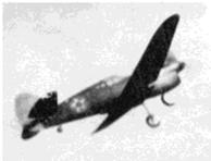
(Above) The model in action gives many thrills; an actual
flight picture
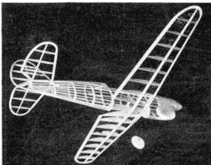
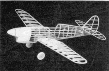
(Below) The frame‑simple light and strong‑ready for the covering
As indicated on the plan, the front portion of the fuselage is filled‑in with pieces of very soft 1/16" sheet. lndividual pieces of balsa are cut so as to fit snugly within the space between the bulkheads and stringers. The extreme front of the nose is shaped from four pieces of 1/4" laminated sheet balsa. Broken lines indicate how the nose is hollowed to receive the nose plug and for lightness. Cement the nose block to the front bulkhead and, when dry, cut and sand the entire fuselage front to a smooth, accurate shape. Where the wing fits in, curved 1/16" thick pieces are cut to fit exactly to the airfoil shape.
It is necessary for the wing to be of strong construction since the landing gear is attached to it. It will be necessary to make a drawing of the left wing so both halves can be assembled directly over full-size plans. Ribs, 1, 2, and 3 are cut from 1/16" sheet while the others are 1/32" sheet. Sand them to, exact and size and cut the notches for spars. Spars and leading edge are cut from sheet stock as indicated and the trailing edge is it tapered 1/8" x 3/8" strip. Tips cut from 1/8" sheet are assembled over the plans. Use pins to hold the various pieces in place until the cement has set. Join the wing halves with 2" dihedral at each tip; then add the single center rib and the several short 1/16" sq. spars. Next attach the 1/4" deep landing gear spar and reinforce the joint necessitated by the dihedral angle. Finish the wing by cutting and sanding edges and tips to conform to airfoil shape.
The landing gear struts are fashioned from .040 music wire. The wire is bent in such a manner as to join the spars and rib 3 as detailed on the drawings. Be sure to, make a right and left strut. With thread bind the struts to the spars and then use a needle and sew right through rib 3 and about the wire. Apply several coats of cement to the thread wrappings and adjacent areas. Incidentally, the rubber tubing covers are not slipped on the struts, until the wing has been covered.
Using a sharp razor blade and sandpaper, wheels can easily be made from laminated discs of hard balsa. Washers or other bearings cemented to the sides will make them revolve freely and accurately.
Tail surfaces come next and both stabilizer and rudder are of similar construction. Make complete frames using 1/16" sheet outlines, 1/16" x 1/8" strips for spars, and 1/16" sq. pieces for ribs. When dry, remove these frames from the jigs and attach 1/16" sq. strips of soft balsa to each side of each rib. Ribs are later cut and sanded streamline and the leading and trailing edges are tapered to conform to the rib shape.
For best flight performance your "Hawk " must have an efficient propeller. Select a hard block and cut out the blank as shown. Drill a hole for the shaft, then start to cut away the back surface of the blades; a bit of undercamber is desirable. Now cut away the front of the blank until the blades are of the desired thickness. Round the tips and reduce the depth of the hub. Use rough and then fine sandpaper to finish the job and bring the blades into balance. Apply several coats of clear dope with light sanding between each to smooth and toughen the wood. Shape the spinner from a light grade balsa block, then notch it so it will fit neatly over the prop hub. Before the spinner is permanently attached, the freewheel gadget should be considered and if none is being used, the propeller shaft must be securely anchored.
The removable nose plug is made of laminated squares of hard 1/8" sheet with a plywood disc at the front. Drill the hole so the thrust line will tilt slightly to the right for proper circle under power. Washers cemented to the front and back of the plug will fix the line of thrust.
COVERING AND ASSEMBLY - Do not be fooled by the pictures of the uncovered structure, the model is not assembled before covering. We always lightly fix the various units together for photographs, then take them apart again. First step in preparing for a neat job is to thoroughly sand the frames to remove all flaws and roughness. Since only those members of the fuselage that run from nose to tail should touch the covering, it is best to sand the bulkheads to a slightly scalloped shape; this can be done with a pencil or other round object with fine sandpaper.
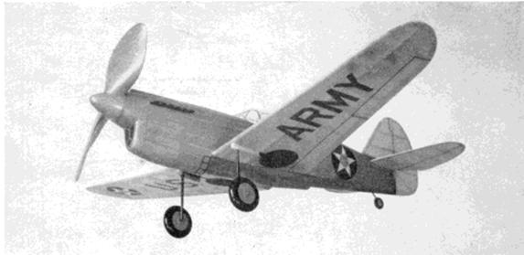
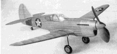
The finished
Hawk P‑401D, with all details of the full scale plane, is a fine flier
Colored tissue is used for all covering and decorations. Dull brown or olive with light blue undersurfaces is the usual color of Army fighters. Cover the wing first, using light dope or banana oil to stick the tissue to the frames. Wings are covered from the second rib to the tips. Attach only the extremities of the areas being covered. Incidentally tips and similar curved parts require separate pieces to help avoid wrinkles. Tail surfaces are covered in the same manner as the wing. Since the fuselage is of a rounded cross-section, it is best to use many small pieces of tissue to prevent unsightly wrinkles from spoiling the job. The cowling and similar wood parts are tissue covered too. Lightly spray all covered parts with water, then pin the wing and tail surfaces to a flat surface to keep them from warping. Clear dope is not applied to the covering until the model is assembled.
The author followed this procedure to assemble his P-40D: First the wing is secured to the fuselage; if the frames have been made with accuracy, this is easy for they will fit together exactly. Secure the wing's position with plenty of cement. The structure shown under the wing in broken lines is next made. Formers are cut from 1/16" sheet to the shape shown and stringers are 1/16" sq. medium stock. Wing root pieces W-R, also cut from 1/16" thick balsa, are fitted from the wing's trailing edge to the fuselage. Since each model will vary a bit, it may be necessary to change the length of these pieces - this is also true of the 1/32" sheet wing fillets. Finish the wing to fuselage and under the wing details by covering with colored tissue to match the other covered parts. To set the stabilizer in position, the rear of the fuselage must be cut and then recemented; be sure to note the slight negative angle of the stabilizer. When cementing the rudder fast, offset it about 1/16" for a right turn. Tissue fillets between the tail surfaces will enhance the appearance. Moisten any wrinkles and permit to dry before applying a coat of clear dope to the entire model.
The numerous minor details are finished next. Rubber tubing of the correct diameter is slipped over the wire landing gear struts and then painted black. Paint the wheels before placing them on the axles; washers soldered to the ends hold them in place. Covers, which hide the undercarriage, when retracted, are made from balsa scraps -- check photos of the model and real plane for more details. The cockpit enclosure is made from thin celluloid. It is best to make paper patterns before cutting the celluloid and be sure to avoid cement smears when gluing to place. Frame details of the cockpit are represented by thin strips of colored tissue doped to place. The stars, U.S. ARMY and similar details are made from colored tissue and the effort required in making them will be amply repaid by the snappy appearance they add to the model. Control surface outlines are represented by thin strips of black tissue doped to the surfaces. Addition of the tail wheel, exhaust ports, radiator detail, wheel wells and numerous other items will aid greatly in making your model more attractive without harming the flying ability. Naturally the propeller, nose block and any other uncolored parts should be painted to match the models covering.
FLYING - Eight to ten strands of 1/8" brown rubber will be needed to power our model "Hawk." Lubricate the rubber strands and then wipe off the excess to prevent splashing the fuselage sides. Hook one end of the loop of strands to the propeller shaft and drop the other ends through the body. It may be necessary to remove a small portion of the covering in the rear to aid in fitting the bamboo pin into position to hold the strands.
If possible, test hop your little pursuit over a grassy field on a calm day to keep from damaging it before necessary adjustments can be made. It is important that the glide is reasonably good before any power flights are attempted so try a few shoulder‑height glides, adding weight to the nose or tail to obtain the desired smooth, flat descent. A few turns on the rubber motor can be tried once the glide seems okay. Minor adjustments can be made by
Slightly warping a wing tip or the tail surfaces but correction for serious misadjustments. should be made at the nose plug by off-setting the thrust line to the right or left, size of circles under power can be controlled and slight down-thrust will iron out a stall. Gradually increase the number of turns making any further adjustments. For maximum flight performance, stretch the rubber and store up power by using a mechanical winder.
Exercise your best judgment in the building and flying of your "Hawk" P-40D and you will be rewarded with an attractive, fine performing model. Many hours of enjoyment are in store once the plane is completed.
VICT0RY
Scanned
from October,1942
Model Airplane News
![]()
![]()
![]()
![]()
[ Home ] [ Previous Plan Pages ] [ Special
Things ] [ Earl Stahl Plans ]