|
|
The Plan Page
[ Home ] [ Previous Plan Pages ]
[ Special Things ] [ Earl Stahl Plans ]
|
|
Build This Flying Replica of the World's Fastest Pursuit Plane-The Bell P-39
By EARL STAHL
LARRY BELL'S "Airacobra," latest and most sensational of the U.S. Army pursuits, its one of the swiftest and deadliest fighters ever to take to the air. With exceptional speed, unusual maneuverability and impressive firepower, it should outperform and out-fight any of the war planes in current production.
Most prominent of the many unusual features of the P-39, as it is designated by the U.S. Army Air Corps, are the tricycle landing gear and location of the engine behind the pilot's cockpit. Use of the three-wheel retractable undercarriage allows the ship to make use of small airports, which is an important factor in war-time operations. The Allison engine of 1090 horsepower is located in the middle of the fuselage, at the position of the center of gravity, and the propeller is driven by a long shaft which passes beneath the pilot's feet. This concentration of weight near the center of gravity aids in making the ship more maneuverable. The fact the engine is not in the nose permits convenient installation of the heavy armament.
The P-39 is probably the heaviest armed single-seater in production for Uncle Sam. Poking out of the ship's bullet-shaped nose is a 37 millimeter cannon which fires one pound shells. Also located in the nose are four machine guns synchronized to fire through the whirling propeller blades. (Airacobras under construction for the Royal Air Force will probably be armed with even more machine guns.)
Another unique feature is found in the cockpit arrangement. To enable the pilot to "bail-out" in the event his plane is disabled, this fighter is equipped with two doors that fall away from the fuselage when a button is pushed.
Performance of the "Airacobra" is indeed remarkable. The top speed is reported to be over 400 miles per hour and the ship can reach an altitude of nearly seven miles. Landing speed is quite slow for this type plane, for it "comes-in" at 70 miles per hour -- about the same speed as a Douglas or Lockheed transport. The fuel load of 140 gallon is sufficient for a flight of 1560 miles.
The proportions of the real plane make possible a graceful model with excellent flight characteristics. Despite the low-wing, pursuit design, the little ship is capable of making stable, efficient flights of surprising duration. When being flown from a smooth, level surface, the tricycle landing gear enables the model to make extremely realistic take-offs and landings. The model, because of its snappy appearance and interesting construction will provide many hours of enjoyment both in building and flying.
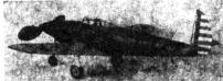
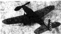
Decorations make it realistic
After becoming familiar with the plans and procedure of construction, you may start to build the -----
Fuselage
Use of the keel pieces cut front sheet balsa simplifies the construction and aids in making the structure more accurate. Trace the top, bottom and side outlines on paper, to obtain the correct shape of the keels. Average depth of the
keels is about 5/32": lightly cement the paper patterns to 1/16" sheet balsa and then use a sharp razor blade to cut them out. The section between bulkheads No.4 and No 6 does not have any support at the cockpit but a curved piece conforming to the wings’ shape is placed at the bottom, as shown. Bulkheads also are cut from 1/16" sheet; two of each are required. It will noticed that only a few of the bulkheads have notches for all the stringers. Cut out the notches shown and mark the positions of the others, which will be cut later as needed.
Pin the keel pieces into position over the plan to begin actual assembly of the fuselage. Cement half the bulkheads to their respective positions; align the bulkheads accurately so they are exactly perpendicular to the keels. Attach one of the side keels and when the cement has hardened remove from the plan and add the remaining bulkheads and the other side keel. Stringers are light-grade 1/16" square strips. As the work progresses it will be necessary to cut many of the notches for the stringers: Use a razor blade that has been broken to a sharp point for this operation. Once a stringer has been attached to one side, always place one in the corresponding position on the other side to avoid pulling the body out of line. Pieces of hard 1/16" sheet cemented between the stringers provide the anchorage for the bamboo pin that holds the rubber motor in the rear.
As indicated on the plan, the front portion of the fuselage is "filled-in" with pieces of very soft 1/16" sheet. Individual pieces of balsa are cut so as to fit snugly within the space between the formers and stringers. An exception is the several sections at the bottom into which the front landing gear fork is fitted; leave these sections open as they can finished later. The extreme front of the nose is shaped from two pieces of 1/4" sheet that have been cemented together. As shown the center of the nose block is cut out to receive the nose plug. Cement this nose block to former No. 1 and when dry cut and sand the entire fuselage front to smooth shape.
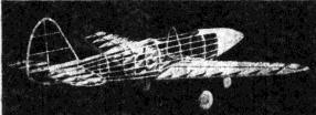
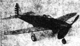
 The framework is simple light and sturdy The nose wheel protects the propeller
|
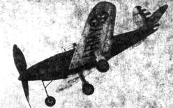
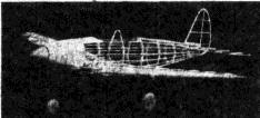
 A large stabilizer makes it stable It is a beautiful flier |
Tail Surfaces
Construction of the tail surfaces is simple; both stabilizer and rudder are constructed in similar manner. The stabilizer is built one piece so a complete plan must made; build directly atop the plans. Cut the outline shapes from 1/16" sheet and pin them to place over the plans. Spars and ribs are 1/16" square stock. When these flat frames are dry remove them from the plan and cement soft 1/16" square strips to both sides of the ribs; these strips are later cut to a streamline shape. Trim and sand the stabilizer and rudder to complete their construction.
Wings
The wing must be of sturdy construction since the rear landing gear struts are attached to it. Ribs are cut front 1/32" sheet with the exception of W-4 which is 1/16" sheet; two of each type rib are required. Notches for the spars and leading edge must be cut with accuracy to insure a neat job. A full-size left wing plan must be made so the parts can be assembled directly over the plans. Sizes of the various spars are noted on the plan. The 1/16" x 1/4" spar to which the landing struts are attached is not placed until the dihedral is added. The wing halves should be joined together accurately and solidly, dihedral at each tip is 1-7/8". Now attach the 1/4" deep spar and reinforce the junction necessitated by the dihedral. Trim and sand the leading and trailing edges as well as the tips to correct finished shape.
Landing Gear
The landing gear as developed for this model is not difficult to construct yet is both accurate in appearance and extremely rugged. Let's complete the front strut first. It is made from .034 music wire. Two pieces are bent to conform to the shape shown on the plan and are then soldered together. The third wire, which braces the front fork, is shaped as shown on the side view and it, too, is soldered to place. Attach the gear to the fuselage structure by sewing the wires, using needle and thread, to bulkhead No. 2; bind the rear brace to the keel. Check for correct alignment and then apply several coats of cement. Finish the nose by filling-in with 1/16" sheet.
Construction of the two rear landing gear struts is also detailed: they are fashioned from .040 music wire. Two separate wires are needed for each unit --- be sure to make a right and left strut. Solder the parts together and then attach them using thread and plenty of cement. Use a needle and sew right through the rib and about the wire. If properly made, this landing unit will really "take it." Rubber tubing covers and other details are not added until the model is covered.
Wheels are made from laminated discs of sheet balsa: all are 3/8" thick. Bearings should be cemented to the sides so they will revolve accurately and smoothly.
Propeller
A hard balsa block 7/8" x 1-318" x 7-1/2" is required for the propeller. Shape the blank as shown and then carve a right hand prop. Cut the back face of the blades first: a bit of undercamber is desirable. The prop blades shape can be determined from the photos. Apply several coats of dope after they have been sanded smooth. Shape the spinner and then notch it to fit accurately over the propeller hub. It is advisable to use a free-wheel device to help improve the glide -- hide it within the spinner. A washer is glued to the back of the prop so it will revolve freely. Color dope to a high finish.
The removable nose plug is shown. A disc of 1/32" plywood forms the front while the back is laminations of balsa. Fix the line of thrust by cementing washers to the front and back of the plug. For the propeller shaft use .040 music wire. Place several washers between the propeller nose plug.
Covering
To properly prepare for a neat covering job the entire frame must first be sanded thoroughly to eliminate all flaws and roughness. Our test model is colored to conform to the regular U.S, Army color scheme -- the fuselage is blue, flying surfaces are yellow, details are black. Some of the real "Airacobras" are all silver in color while newest ones are camouflaged with a dull, dark color above and light color below. Colored tissue is best suited for this job since it is both attractive and light in weight. Cover the fuselage first: grain of the paper should run from nose to tail. Banana oil or thin dope is used to stick the tissue to the frames. Numerous small pieces must be used to prevent wrinkles but the individual pieces should be lapped neatly. The nose and similar parts should be covered with tissue, too. Cover the wing and tail surfaces using an individual piece for each side of each unit: grain of the paper runs spanwise. Tips, etc., require separate pieces of tissue also. The parts are lightly sprayed with water to tighten the tissue but are not doped until the model has been assembled.
Assembly
The various parts should now be assembled. Slide the wing into the recess between bulkheads No. 4 and No 6, if the structure has been reproduced accurately the incidence will automatically be correct. Check carefully for correct alignment and then cement the wing fast. Wing root pieces are cut from 1/16" sheet balsa and are fitted between the wing and fuselage. Fillets are cut from very soft 1/32" sheet. The pattern shown indicates the fillets' shape on the original model but since most models will vary a little, paper patterns should be cut to fit YOUR model exactly before the sheet balsa ones are cut. Once fillets are cemented to place, the several small openings at the junction of the body and wing should be "filled-in" with scraps of soft 1/16" sheet. Sandpaper smooth and cover the fillets with blue tissue. It will be necessary to temporarily cut the rear of the fuselage to admit the stabilizer which is attached at the exact angle shown. Offset the rudder a bit to counteract torque. Tissue fillets are placed between stabilizer and rudder. Any wrinkles in the covering should be moistened with water and permitted to dry before the entire model is given a coat of clear dope. Dope should be applied in a dry room to minimize the chance of "blushing."
Addition of numerous details completes the construction. The cockpit enclosure is made from thin celluloid. Shown on the plan is the scale shape for the windshield but since it would be so difficult to reproduce it exactly to scale, it is recommended that the rounded section be eliminated and the enclosure be made as shown in the photos. Make paper patterns before cutting the celluloid and avoid cement smears when cementing to place. Rubber tubing of about 1/8" diameter is slipped over the rear landing gear struts. To cover the front landing strut it will be necessary to split the tubing and then recement it once it is in place; tubing of smaller diameter covers the back brace and fork portion of the front strut. Wheels are held to place by washers soldered to the rear struts -- spring the fork apart to admit the front wheel. Wheel covers are cut from 1/32" sheet and covered with colored tissue to match the other parts. The stars, rudder stripes, U.S. ARMY Etc., are all made from colored tissue and the effort required in making them will be amply repaid by the snappy appearance they add to the model. Control surfaces, flaps and the door outlined by thin strips of black tissue. Exhaust ports, wing walks and other details found on photos of the real ship can be added.
Flying
Eight or ten strands (four or five loops) of 1/8" brown rubber should be used to power this model. Lubricate the rubber and then wipe off the excess to prevent its splashing on the fuselage sides. Attach one end of the motor to the prop shaft and then drop the other end through the fuselage. It may be necessary to remove a small portion of the covering to aid in fitting, the bamboo pin into position to hold the rubber strands.
Probably the most important single factor in obtaining fine flights from any flying scale model is patience. A well-built model, if properly handled, will provide many realistic flights with little or no damage to the model itself. It is important that the glide be reasonably good before any power flights are attempted; select a grassy field for these tests. Try a few should-height glides and, if necessary add a small corrective weight to the nose or tail to obtain a smooth flat glide. Try a few power turns once the glide seems okay: minor adjustments may be made by slightly warping a wing tip or the stabilizer as the case may be, but correction for serious misadjustments should be made at the nose plug. Right or left thrust will control the size of circle while under power, and slight down-thrust will iron out a stall. A mechanical winder should be used for maximum flight performance.
Our "Airacobra" is not only pleasing to the eye from the standpoint of appearance but it is a capable flyer. This little ship is a stable, consistent performer and it makes a picture when in flight. You are bound to find that the distance covered is far more then might be expected for this type of ship.
Scanned from June 1941
Model Airplane News
![]()
![]()
![]()
![]()
[ Home ] [ Previous Plan Pages ] [ Special
Things ] [ Earl Stahl Plans ]