Model
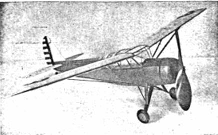
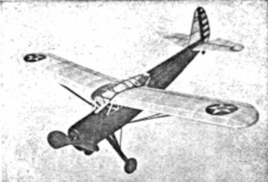
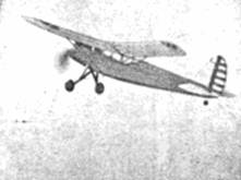
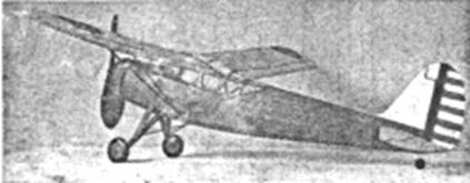
builders will recognize the Stinson 0‑49 as an excellent subject for a flying
scale contest model. In appearance it is attractive yet not difficult to
build. Best of all, the aerodynamic proportions are near perfect; our test
model was built to scale and it was unnecessary to even increase the wing's
dihedral or enlarge the proportions of the tail surfaces to obtain long,
stable flights. The relatively long fuselage permits use of a powerful motor
of considerable length, thus increasing the length of power flights. To make
possible use of a propeller of sufficient size the landing gear is
shown in the extended or flight position. In addition to its excellent flight
qualities, the Stinson offers a wealth of detail to be reproduced in the
radial motor, cabin windows, etc., for those who seek maximum "scale" points
in flying scale contests.
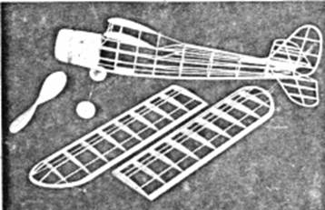
Fuselage
The
fuselage underframe is constructed first; it is shown lightly shaded on the
plan. Work directly over the plan and make two side frames; longerons and
uprights are 3/32” square balsa. While the curvature of the lower longerons is
not excessive, it is advisable to steam them to shape so they will not have a
tendency to draw the upper longerons out of alignment when removed from their
jig. When dry, the side frames are joined by 3/32" square cross‑pieces. Check
frequently to assure proper alignment of the entire structure.
With
exception of the cabin formers, the fuselage formers are cut from soft grade
1/16" sheet balsa. It will be noticed that some of the formers lack notches
for the stringers, and where this is the case the stringers are attached
directly to the sides, as shown. Cement formers to their respective positions
and then add the 1/16" square stringers. The stringers that extend along the
sides are cemented directly to the underframe.
Because of
the cabin's unusual shape, special care must be exercised to insure accuracy
and strength. Full size cabin formers are shown and they are made from hard
grade 1/16" sheet. Assemble the parts of formers C‑1 and C‑4 directly over the
plan ‑ they must be exact. Looking at the side view of the fuselage, it will
be noticed that C‑1 is attached at an angle to the top longeron. Cut a
cardboard pattern to exact angle, to aid in accurately attaching the front
member to place. Cement C‑1 and C‑4 to place and then cut two ribs to shape
indicated on the side view; assemble them to the notches in the formers. If
you have reproduced the structure with greatest care, the ribs will have the
correct incidence 2‑1/2 degrees positive. Attach the other formers and the
3/32" square pieces that form the cabin. Thoroughly recement all joints.
To
effectively represent the metal nose of the real ship, the front from section
No. 1 to No. 2 is covered with soft 1/32" sheet. Two 1/8" sheet balsa discs
are cemented to the front of section No. 1 and then shaped as indicated. The
engine cowling is made in a similar manner. A frame consisting of two circular
bulkheads and four 1/16" square spacers is assembled as indicated by the
broken lines; this structure is covered with 1/32" sheet. The rounded nose
section is made from laminations of 1/8" sheet, the centers of these discs
being removed to the extent indicated by broken lines. Details of the nose
plug are indicated. The removable section is made to fit accurately to the
crank case which is cemented within the cowl front. Finish the nose and cowl
by sanding to finished shape but do not cement the cowl to the nose until
later.
Landing Gear
Before
constructing the landing gear full size sketches of the various wire parts are
made; these parts are bent from .034 music wire. With needle and thread sew
the top member of the front unit to the fuselage longerons and cross‑member.
Since the nose is covered with sheet balsa, long nose pliers will probably
prove helpful for working the needle about the wire and through the formers.
The other two wire units can be temporarily held to place until the parts are
accurately fitted and the whole structure properly aligned. Neatly but firmly
solder the struts together. Securely bind the rear struts to the lower
fuselage stringer, then reinforce the area with 1/16" sheet, as shown. The
center strut is not attached to the fuselage, it being left free to twist and
spring and thus absorb shock. The balsa and rubber tubing fairings are not
attached to the landing gear until later.
Wheels are
made from laminated balsa discs or they may be purchased. Bearings should be
cemented to the sides so they will revolve smoothly and accurately.
Wing
Because of
limited space a full size wing plan could not be reproduced, so a full scale
layout should be made on a large sheet of paper and work done directly over
it. Taper and sand the trailing edges before pinning them into position over
the plan. Ribs are cut from light grade 1/20" or 1/16" sheet; sixteen regular
and two tip ribs are required. Pin ribs to position and then attach the
leading edges and spars. Assemble tip pieces, which are cut from 1/8" sheet,
and cement them to place. Once the leading edges and tips are trimmed and
sanded to shape the wing frames are completed.
Tail Surfaces
Construction of the tail surfaces is quite simple. Both rudder and stabilizer
are made similarly, the plans being nearly self‑explanatory. Make the
stabilizer in one piece. The streamline rib shape is made by gluing 1/16"
square strips of a soft variety to both sides of the underframe and later
cutting them to shape. This manner of construction is strong yet light.
Carefully trim and sand the parts so a smooth covering job can be made.
Propeller
Carve the
propeller from a very hard balsa block 8" x 1‑1/2" x 1"; lay out the blank as
shown. Always cut the back face of the blades first. The hardness of the wood
will determine the thickness of the blades, its shape can be seen on the
photos. Thoroughly sand the propeller and then apply several coats of clear
dope with light sanding between each coat to produce a nice smooth finish.
Equip the prop with some kind of free‑wheel device so the glide will be
improved.
The
propeller shaft is bent from .040 music wire. Place several washers between
the prop and nose plug and bend a loop on the front of the shaft into which a
mechanical winder can be hooked.
Covering and Assembly
Before
starting to cover your Stinson the entire frame should be lightly but
thoroughly sanded to remove all roughness. The several flat windows between
sections C‑1 and C‑4 are covered with cellophane at this time --other windows
are celluloid and not added till later. Being an Army plane, standard blue and
yellow colors are used. Use banana oil for adhesive and cover the fuselage
with blue tissue; to prevent wrinkles numerous small pieces of tissue should
be used. The sheet‑balsa‑covered nose and cowl are tissue covered, too. Wings
and tail surfaces are covered with yellow tissue; grain runs spanwise. Tips,
etc., require separate pieces. The parts are lightly sprayed with water to
tighten the tissue but are not doped until the ship has been assembled.
To
assemble your 0‑49 follow this procedure: Finish the cabin windows first. Use
the very lightest celluloid available -- film negatives boiled in water to
remove the emulsion are excellent. Start at the back and make accurate paper
patterns of each section, cut the celluloid to shape and cement to place,
being careful to avoid cement smears. Pattern for the front windshield is
given but it may need slight altering to exactly fit your model. Thin strips
of tissue doped to the windows, as pictured, will improve its appearance.
Finish the
landing gear by cutting the balsa covers from 1/8" x 1/2" soft balsa; these
members are streamline in cross section. Cut 1/16" deep grooves in the struts
to hide the wires and cement the wires fast; do not, however, attach the tops
of the struts to the fuselage. Cover the struts with several layers of colored
tissue. Split the rubber tubing, slip on the rear struts and then recement.
Wheels are colored and held to place by washers soldered to the axles. It will
be necessary to temporarily cut the tail post to admit the stabilizer, which
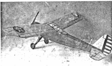
is attached by cement at the angle shown. The rudder is off set 1/16" so the
model will glide in right circles. The wings are fitted to the fuselage with
tips elevated 1‑1/2" ‑‑ scale dihedral. The "vee" wing struts are shown half
size on the plans; they are 3/32" x 3/16" balsa cut streamline. Struts join
the wings at the "X". If the builder wishes to add engine details within the
cowling it is best done before the unit is cemented to the nose. Now that the
model is assembled, a coat of clear dope is applied to all the covered
surfaces.
Minor
details are usually the features that make the model really attractive. The
0‑49, an Army ship, of course should have the regular wing stars and rudder
stripes. These can be made from colored tissue as can the "U. S. ARMY" on the
wing's under‑surface. Control surface outlines, flaps and slots, etc., are
represented by thin strips of black tissue. As noted before, engine details
within the cowling will go a long way in adding to the ship's attractiveness.
Naturally the propeller and other exposed wood parts are color doped.
About ten
strands of 1/8" brown rubber are required to power this model. Measure the
strands to the correct length and attach them to the prop shaft loop. Drop the
rubber into the fuselage and slip the bamboo pin into place to attach the
rubber in the rear. Your model of the Stinson 0‑49 is now ready for its first
flights.
Flying
Select a
calm day and a grassy field for the test flights. However, before taking the
ship to the flying field, it should be made to balance by adding weight to the
nose or tail, until it rests on an even keel when held at the center of the
wing's chord. Test glide the plane and readjust the weight, as necessary, to
obtain a nice smooth glide. Once the glide is satisfactory, try short power
flights and if any corrections are required, make them by offsetting the
thrust line. A sliver of wood at the top of the nose plug tilting the thrust
line down at a slight angle will probably "iron out" a stall, while right or
left thrust will adjust the circle during the power flight. While under power,
circles should be large and to the left; in the glide it should turn to the
right. A little effort and caution will reward you with a fine plane which is
truly attractive yet a remarkable flyer.