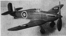
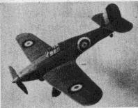
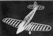
 Realistic and exact in every line |
 A remarkable flier though simply constructed |
The Plan Page
[ Home ] [ Previous Plan Pages ]
[ Special Things ] [ Earl Stahl Plans ]
|
Realistic and exact in every line |
A remarkable flier though simply constructed |
HAWKER "HURRICANE"
 Insignia Is very effective |
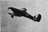 Just like the big ship in flight |
THE Hawker Hurricane, famed British fighter, won the "Battle of Britain" hands down and thus, it is believed, saved the world from the dictators. In Africa, Hurricane "can-openers" armed with 40mm cannon received Gen. Montgomery's thanks for making his historic victory possible. Now overshadowed by its young nephew, the Typhoon, the Hurricane is still blasting the enemy around the four corners of the globe.
Latest versions are capable of nearly 400 miles per hour and carry two heavy bombers in the Hurribomber version. Types fitted with deck arrestor gear are known as Sea Hurricanes and many are operating from escort carriers along the Allied supply routes to England.
Various combinations of armament, eight machine-guns of .303 caliber, four cannon of 20mm bore or two cannon of 40mm bore are used, each designed for a specific job.
The model described here is a speedy flying reproduction of its capable prototype. Because of sleek lines and interesting construction, it will provide many hours of enjoyment both in building and flying. Construction is not difficult; study the plan thoroughly and read the instructions before beginning actual work. Build directly over tracings of the plans and be sure to cement all joints firmly.
Fuselage
To simplify construction and alignment, the keel and former method is used. Obtain the keel pieces' proper shape by tracing the side view top and bottom outlines on a sheet of paper - depth of each keel piece is about 5/32". Cut out the paper patterns and then lightly cement them to 1/16" sheet balsa so they can be cut out. The side keel shape is indicated on the top view; two are required; they also are cut from 1/16' sheet. The various fuselage formers are shown on the plan; two of each type will be needed. Medium grade 1/16" sheet is used for them. Cut only the notches indicated; other notches should be marked and then cut later as required.
Pin the top and bottom keels to place over the side plan and then cement half the formers to their respective positions. Attach the side keel after checking each former for correct alignment. When dry, remove this simple frame from the plan and attach remaining formers and side keel. Stringers are medium grade 1/16" sq. strips. As work progresses it will be necessary to cut many notches for the stringers; use a razor blade that has been broken to a sharp point for this operation. Once a stringer has been attached to one side always attach one to the other side's corresponding position to avoid pulling the structure out of line. Small pieces of hard 1/16" sheet cemented between stringers in the rear serve as the anchor for the rubber motor.
"Filling-in" the nose with balsa, as shown, effectively represents the metal cowl of the real ship. Use soft 1/16" and 3/32" stock, as required, and cut the individual pieces to fit snugly within the spaces between stringers and formers. When dry, cut and sand the entire nose to a smooth, accurate shape. The extreme front part of the nose is cut front 1/4" sheet that has been laminated together. Notice the nose block center is cut out to receive the removable nose plug. Cement the block to former 1 and then shape it to blend with the nose.
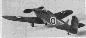
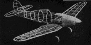 The frame work is orthodox, and sturdy though light |
 A heavy nose gives balance and strength |
Wing
The wing is constructed in three parts; plans for the right wing and half the center section being given. Prepare complete plans for the center section and left wing so parts can be assembled over them. Two of each type ribs, with the exception of 1 and 1 - B, are required; ribs are cut from 1/32" or 1/20" sheet. Notches for the various spars must be cut with accuracy to insure a neat job. Leading edges of the outer sections taper from 1/8" by 1/4" to 1/8" sq.; taper the trailing edges to correct crosssection before pinning them to place over the plans. Assemble the various parts directly on the plan, using pins to hold them in place until cement has hardened. The end ribs of each section should be slanted a small amount so the dihedral angle will be correct when they are joined. Tips are cut from 1/8" sheet and cemented to place. Trim the edges and tips to shape and then cement the three units solidly together with 1-7/8" dihedral at each tip.
Landing Gear
The landing gear, as used on this model, is sturdy yet easily reproduced. Check the various plans and photos for details. Two pieces of .040 wire are required for each strut and these are soldered together to form a strut as shown by the perspective; be sure to make a right and left unit. Attach the gear to place with thread wrappings about the 1/4" deep spar, and by sewing with a needle and thread right through the ribs and about the wire. Thoroughly cement thread bindings and all adjacent areas.
Wheels may be purchased or they can be made from laminated 1/8" sheet of the hardest variety. They are 3/8" wide. Cement washers to both sides of each wheel so they will turn freely and accurately.
Tail Surfaces
As is usually true of fighting planes, the tail surfaces are too small to insure stable model flights, so surfaces' proportions are enlarged a small amount. Both stabilizer and rudder are constructed in like manner and while only half the stabilizer is shown, it is constructed in one piece. First build complete frames using 1/16" sheet for the outlines, 1/16" x 1/8" strips for the spars, and 1/16" sq. pieces for the ribs. When these assemblies are dry, they are removed from the plans and 1/16" sq. strips are cemented to both sides of the ribs. These pieces are later cut to form the streamline rib shape. Trim and sand the frames to complete the construction.
Propeller
For best flight performance the model must be equipped with an efficient propeller. Select a hard block 8" x 1-1/2" x I". Drill the tiny hole for the shaft and then cut the blank as shown. Cut the back face of the blades first; a bit of undercamber is desirable. The blades shape can be determined from the photos. Apply several coats of dope with light sanding between each to get a smooth finish. Shape the spinner from soft balsa and then notch it to fit accurately over the hub. A free-wheel device, if used will improve the glide - hide it within the spinner. A washer should be cemented to the back of the prop to permit it to revolve freely. Color dope to a nice finish.
The removable nose plug is shown. A disc of 1/32" plywood forms the front portion while the back is laminations of 1/8" sheet balsa. Drill a small hole through the center and cement washers to both sides to fix the line of thrust. Bend the prop shaft from .040 music wire. Several washers should be placed between the prop and nose plug to reduce friction.
Covering
For finest appearance a smooth, attractive covering job is necessary. Before starting to cover, work over all the frame with fine sand paper and remove all flaws and roughness. On the fuselage only those members which run fore and aft should touch the covering, so lightly sand the formers to a slightly scalloped shape to aid in making a better job. Colored tissue is used for the covering, attached to the frame by light dope or banana oil. The model pictured is colored all red but ships at war are camouflaged in greens and browns.
Cover the fuselage first, using numerous small pieces to help prevent wrinkles; lap each piece neatly. The nose and similar wood parts are tissue covered, too. Use a separate piece of tissue for top and bottom of each section of the wing and tail surfaces; it is not necessary to attach the tissue to all the adjacent frame. Wing tips, etc. require individual pieces. Once all parts are covered lightly spray them with water to tighten the tissue, but do not apply any dope until later.
Now, to assemble the various parts: Fit the wing into the recess and cement it fast if the structure has been reproduced with accuracy the angle of incidence will automatically be correct. Finish the undersection from wing to fuselage with pieces of 1/16" sq. Wing root pieces, as shown, are cut from 1/16" sheet and attached between wing and fuselage. Fillet pieces, to be cut from 1/32" sheet, are shown on the plan. The pattern indicates the fillets shape on the original model but since most planes will vary a little, paper patterns should be cut to fit your model before sheet balsa ones are cut. Once they have been cemented to place, the fillets are covered with colored tissue, as is the uncovered portion tinder the wing. The stabilizer is attached in position shown and at angle indicated. Off set the rudder a small amount so the model will glide to the right. Check and recheck tail surfaces for correct alignment. Tissue fillets are placed between the stabilizer and rudder. Any wrinkles in the covering should he moistened with water and permitted to dry before the entire model is given a coat of dope. If a small quantity of the same color dope as tissue is added to the clear dope, it will give an attractive finish.
There are numerous other details that should be added before the model can be considered complete. The cockpit enclosure is made from thin celluloid. Make paper patterns by the "cut and try" method before cutting from celluloid; be sure to avoid cement smears when attaching to place. The structural detail is made by doping thin strips of black tissue to the transparent enclosure. Two pieces of 1/8" rubber tubing (as used on electrical appliances, etc.) are slipped over the vertical portion of the landing gear wires. Wheels are colored and then held to place by washers soldered to the axles. The outer landing gear covers are cut from 1/32" sheet and then covered with colored tissue to match the plane. The red, white and blue British insignia on the original model was made from colored tissue. Control surface outlines, flaps, etc. are thin strips of black tissue doped to the covering. Make the small sub-rudder and tail wheel from sheet balsa. Exhaust stacks and other details found on photos of the real ship can be added without harming the model's flying ability.
Our model is powered by 10 strands (5 loops) of 1/8" flat, brown rubber. Hook the motor to the propeller shaft and then drop the other end through the fuselage. It may be necessary to remove a small portion of the rear covering to get the strands in position to be held by the removable bamboo pin. The model Hurricane is now ready for its initial flights.
Flying
Test the model over deep grass but if none is available make first flights R.O.G. with a few turns. In all probability the ship will be slightly tail heavy; if so, add a small amount of weight to the nose. As correct balance is obtained, increase the number of turns. Off-setting the thrust line to the right or left will aid in controlling the amount of circle in either direction. For maximum flight performance, stretch the rubber motor and wind with a mechanical winder.
The Hurricane is a trim little craft, light in weight and speedy in flight. It should make a worthwhile addition to any builder's collection.
Happy landings!
Scanned from
Flying Scale Models
[ Home ] [ Previous Plan Pages ] [ Special
Things ] [ Earl Stahl Plans ]