The Plan Page
[ Home ] [ Previous Plan Pages ]
[ Special Things ] [ Earl Stahl Plans ]
gt-hunter1@home.com
MISTER
MULLIGAN JOINS THE NAVY
A realistic high performance scale
model of the
new Navy Howard personnel transport plane.
by EARL STAHL
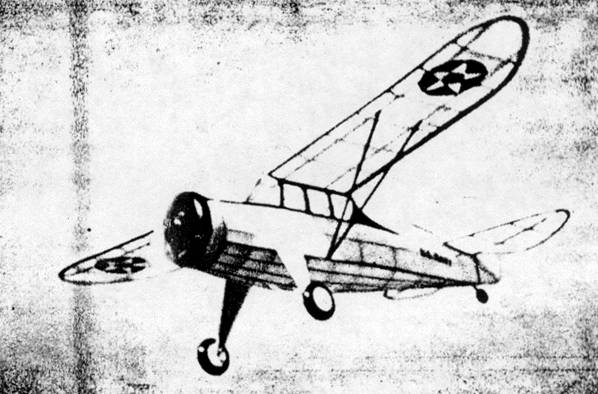
Designed carefully to scale for consistent stable flights
while the frame is
light but strong. In flight the resemblance to a large ship is startling.
While the transport planes do not have the spectacular appeal of fighters, Scouts and dive bombers, they are a most necessary part of naval aviation. Essentially these "workhorses of the flying fleet" are adaptations of commercial ships, their mission being to provide aerial services of all kinds.
One of the latest type planes to be acquired by the U.S. Navy for light transport duty is the Howard GH-1. Ideally suited to this task, it has a convertible cabin for passengers, cargo, a stretcher for patients, space for mail or express, or for use in aerial photography.
Howard airplanes were developed from Ben Howard's famous racer "Mister Mulligan", winner of both the Thompson and Bendix Trophy races in 1935. Remarkably similar to the race plane prototype. Howard military and commercial transports are noted for their outstanding performance, ruggedness and ease with which they are flown.
Few details have been released on the navy GH-1; however specifications of the commercial, five passenger Howard DGA-15P should prove fairly accurate. This 450hp. Wasp Jr. equipped monoplane can cruise at 201 mph for 980 miles on 115 gallons of fuel. Initial rate of climb is nearly 2,000 ft. per min. and the service ceiling is 22,000 feet. Useful load is 1,700; gross weight 4,350 pounds.
The model plans have been carefully prepared so they will serve either as the basis for a flying or scale model. Proportions of the real plane make possible an attractive model with exceptional flying characteristics. You are sure to be fully satisfied with the stable, swift flights of this little ship if you build it according to these instructions.
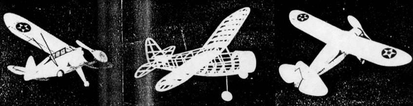
Construction: A simple rectangular frame is the backbone of fuselage structure; it is shown lightly shaded on the plans. Work directly over the plans, or better still, tracings, and build two side frames, one atop the other to be certain they are identical. While it is not absolutely necessary, it is best to steam or soak the longerons in hot water so they will dry to a natural curve and thus help in keeping the structure from springing out of shape. Hard grade wood is used and longerons and uprights are 3/32" sq. stock. Invert the completed sides over the top view and cement 3/32" sq. pieces to place at the center of the body; when dry, draw the backs together and place the remaining cross-pieces. It will be necessary to crack the longerons in the front so they can be pulled into the positions shown on the plan.
Cut the various formers from 1/16" sheet and now if the basic structure is dry, it should be removed from the work board and formers attached to their correct positions. Center section is assembled and cemented to the fuselage frame; do this accurately as the wing's correct placement is determined by its position. Since stringers are merely fairing strips, they should be medium-soft balsa. Stringers are cemented directly to the underframe except where there are formers, of course, and where there are no notches in the formers; they are cemented right to the sides.
The engine cowling is made next. A frame consisting of two circular 1/16" sheet bulkheads and four 1/16" sq. spacers is assembled as indicated by broken lines; this structure is covered with 1/32" sheet. The rounded nose section is made from laminations of 1/8" sheet; the centers of these discs being removed to the extent shown. Details of the nose plug are indicated. The removable section should be made to fit accurately to the crankcase which is cemented within the cowl front. Finish the nose and cowl by sanding to finished shape but do not cement the cowl to the nose until later.
The landing gear unit can be made at this time; it is bent from .040 music wire and formed to shape and size shown. Using thread bind the wire unit to the fuselage underframe. Add the triangular 1/16" sheet gussets shown and then apply several coats of cement. Although the 1/8" balsa struts are not added to the landing gear at this stage of construction, they can be cut out. These struts are streamline in crossection and have a groove in the back to conceal the wire.
Pieces of hard 1/16" sheet cemented between the rear fuselage members provide anchorage for the bamboo pin that holds the rubber motor in the rear.
Not only a stable flier but most realistic
Only the right wing plan is shown so it will be best to prepare a full scale drawing of the left panel in order that construction can be done directly atop it. Using patterns given, cut the regular and tip ribs from 1/32" or 1/20" sheet. Pin all like ribs together and sand them uniformly, then very accurately cut the notches. Pieces for the tips are cut from 1/8" thick sheet and assembled over the plan. Taper the 1/8" x 3/8" trailing edges before pinning to place over the drawings. Ribs are kept in proper alignment by pins. Spars are hard balsa strips, all of them being 1/16" sq.; leading edge is 1/8" x 1/4". Slant the inner ribs a bit so the dihedral angle will be correct. Cement all joints firmly, then when dry, remove from the plans and finish the edges and tips by trimming with a razor and sandpapering.
Making the tail surfaces is easy and both the rudder and stabilizer are constructed in a similar manner. In the interest of greatest strength the stabilizer is built in one piece so a complete plan must be drawn. Outlines of the surfaces are cut from hard 1/16" sheet stock and spars are 1/16" x 1/8" strips. Ribs are lengths of 1/16" sq. when dry, frames are removed from the plans and soft pieces of 1/16" sq. cemented to each side of the ribs; these are cut streamline once the cement has hardened. Trim and sand the surfaces to their final shape.
Shown in perspective is the propeller blank. Select a hard block of the proper size and then shape the blank as indicated. Drill the tiny hole for the prop shaft before starting to carve a right-hand propeller. Hardness of the block will determine the blade's thickness, the shape of which can be seen in the photos. Thoroughly sand the propeller to balance and smooth the blades, then apply several coats of light dope with light sanding between each to produce a nice finish. Equip the air screw with a free-wheel device of some sort to help improve the glide. A washer is cemented to the back, too.
For the propeller shaft use .040 music wire. Fix the thrust line through the nose plug by cementing washers to both sides then slip the nose plug, several washers, and propeller on the shaft in the order given. A loop is bent in the end of the shaft into which a winder can be hooked.
Covering and assembly: Probably the most important item for a fine appearing model is a neat covering job. Before starting to cover your Howard, the entire frame should be lightly but thoroughly sanded to remove all roughness. The flat side windows are covered with thin cellophane at this time; the front windshield is celluloid and is not added 'til later. Either colored tissue or light grade silkspan may be used -- color of the real plane is silver but other colors to suit the builder may be employed. Cover the fuselage first using light dope or banana oil for adhesive. On curved parts numerous small pieces of covering will be required to prevent unsightly wrinkles. Use an individual piece to cover each side of each wing and tail section. The balsa cowling and similar parts are tissue covered too. Once covered, all parts are lightly sprayed with water to tighten the covering; to keep the wings and tail surfaces from warping they should be pinned to a flat surface until dry. Clear dope is not applied until later.
Next the various parts are assembled. A half windshield pattern is given. It is best to make a complete paper pattern to check for exact fit before cutting one from celluloid. Avoid cement smears when attaching the windshield.
Completion of the landing gear unit is easy. Flow cement into the groove of the previously made fairing struts and fir them over the wires -- do not, however, attach the tops of the struts to the fuselage structure. A strip of silk cloth over the strut and wire will keep it from coming loose. Colored tissue should be doped to the struts so they will match the fuselage. Wheels are made from laminated sheet balsa or they may be purchased. Wheel pants improve the appearance but since they are optional equipment on these planes, we eliminated them in the interest of lighter weight and better flights. Color the wheels and then attach them to the axles by soldering a small washer to the ends. The thin center struts are rounded pieces of bamboo.
Care must be exercised when assembling the surfaces to the fuselage. It will be necessary to temporarily cut the rear of the fuselage to get the stabilizer in place; it is parallel to the workbench. A tissue fillet is fitted between stabilizer and body before the rudder is set in position. Offset the rudder a bit for right circle in the glide. Tips of the wings are raised 1-1/8" for proper flight stability; be sure they are cemented securely. Wing struts 1/16" deep are shown and they should be assembled and painted before being attached. The entire model is given one or two coats of clear dope.
Add the various more minor details to "dress-up" your Howard and the construction is finished. Naval insignia, cabin trim, cowl decoration, etc. are all made from colored tissue of a contrasting shade. Control surfaces, a door and the like are effectively represented by thin strips of black tissue. If the builder wishes, engine details can be placed within the cowling. The tail wheel and similar items are made from scraps of balsa. Naturally the propeller and similarly exposed wood parts should be colored to match the model's color scheme.
Flying: About six strands (three loops) of 1/8" flat brown rubber will be required to power the little ship. Measure the strands to right length and then attach them to the loop on the prop shaft. Drop the other ends through the nose and slip the rounded bamboo pin through the fuselage to attach them. It may be necessary to remove a small section of covering to do this. Your Howard naval transport is now ready for its first flights.
To get maximum flight performance from any model, it must be properly adjusted. Even the most carefully built planes usually require some minor corrections so go about this with caution. Before going to the flying field, the ship should be made to balance on an even keel when held at the wing tips; this is done by adding weight to the nose or tail. A grassy field free from obstructions is best for flying this or any other model. Test glide and make any weight readjustments necessary to get a nice, smooth descent. Once the glide is satisfactory, try short power flights and if any corrections are needed, make them at the nose plug by offsetting the thrust line. A sliver of wood between the top of the nose plug and crankcase, tilting the thrust line down, will probably "iron out" a stall while right or left thrust will make it circle as desired while under power. Under power circles should be large and to the left; in the glide it should turn to the right.
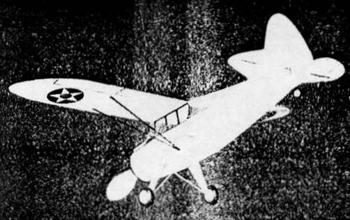
The original model is pleasing to eye from the standpoint of appearance and it is an unusually capable flyer. It makes a picture when on display or in flight and is sure to please the most exacting fan.
VICTORY
Scanned
From August, 1942
Model Airplane News
![]()
![]()
![]()
![]()
[ Home ] [ Previous Plan Pages ] [ Special
Things ] [ Earl Stahl Plans ]