The Plan Page
[ Home ] [ Previous Plan Pages ]
[ Special Things ] [ Earl Stahl Plans ]
The Hurricane!
In the August, 1939, issue just eleven months ago - we
presented the "Hi-Climber." Well, since that time letters have been coming in by
the sack-full asking for another Earl Stahl model. And now, balsa fans, we've
got one for you that matches the "Hi-Climber's" performance in every respect-the
"Hurricane!"
By Earl Stahl
Author of "A Top-Notch 'Hi-Climber' "
HERE'S A MODEL that's the result of two years experience with low wing -
designs. And in it are crystallized - the desired characteristics for stable,
consistent flights. The craft has been flown hundreds of times, in all kinds of
weather, without crashes of any sort. When winder - wound, the climb is
interceptor - like, being nearly vertical. This job, like most low-wingers, goes
from the power flight to the glide without any tendency to dip or stall. Flights
in calm evening air average 1 min., 38 sec., but when aided by "risers" the
length of flight is considerably longer.
Most parts are shown full size on the drawings, so little difficulty should
be experienced in duplicating this plane. Trace the plans so work can be done
directly atop them. Don't cut or deface the magazine pages, and, where
necessary, enlarge the plans to full size.
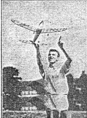
Why is Earl Stahl pointing? Well, he's indicating the path the "Hurricane"
always takes -- up! |
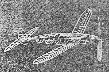
It's easy to see from this photo that the "Hurricane" is designed both for
speed and strength.
And. as in all ships Earl turns out. simplicity is the byword. What's more his
easy - to - follow instructions will make it a cinch for even, beginners to construct top -
notch models from the graphic plans given here. |
FUSELAGE AND LANDING GEAR
THE BODY consists of a rectangular under-frame to which the formers and
stringers are added. The shaded areas of the side view indicate the part to be
constructed first. Incidentally, it is advisable to make the tail-piece integral
with the fuselage, and then it can be cut off after the entire unit is
completed.
Work directly over the plan and make two sides, one atop the other, from
medium grade 1/8" sq. balsa. The glue will probably cause them to stick
together, but they may be separated by a razor blade. Set the sides erect over
the top view and join them with 1/8" sq. spacers as indicated. Work carefully
and line everything up correctly.
Bulkheads - halves of which are shown on the plans-are cut from 1/16" sheet
balsa and are glued to their respective stations. You will notice that most of
the bulkheads have no stringer notches, so glue the 3/32" sq. stringers directly
on the formers.
Bend the landing gear from a single piece of 1/16" diameter wire. Bind the
gear neatly into position with thread. Wheels, made from laminated balsa, are
fitted with brass washers which serve as bearings. Washers soldered to the axles
will hold the wheels in position.
Shaded areas in the front and rear are filled with 1/16" sheet balsa to
provide a suitable place to hold the model while winding. Thin aluminum plates
are cemented securely to the sheet balsa in the rear. These plates serve to
cradle the hardwood dowel pin which is fitted through the fuselage to hold the
rubber motor. Scrap balsa is used to form the cockpit. Once the tail piece is
cut off, the fuselage construction is complete.
WING AND TAIL
EIGHTEEN ribs are cut from 1/16" sheet to the exact shape shown on the plans.
Fit the various sized spars carefully into the notches, and cement the - hard
leading and trailing edges into place. Wing tips, cut from 1/8" sheet balsa, are
now cemented into position. When dry, the leading and -trailing edges, as well
as the tips, should be trimmed and sanded to the indicated shape. The tail
surface construction is very simple. A typical stabilizer rib is shown, and the
smaller ribs are formed from it. The top spar is located after the ribs are
pinned into position. Select medium-grade wood for the tip outlines and the
trailing edge.
The rudder is formed from 1/8" thick outlines and 1/8" by 1/8" spars and
ribs. When dry, it is lifted from the plan and the 1/16" by 1/8" pieces are
glued to both sides to form the streamlined shape. This manner of construction,
which is used for all tail surfaces, is very strong and light.
COVERING AND PROP
BEFORE starting to cover the various parts, it is advisable they should be
carefully sandpapered to remove any roughness, and flaws.
Banana oil is used as the adhesive to fasten the colored paper to the frames.
The grain of the paper should run lengthwise on all surfaces. Stick the paper to
every rib and spar of the wing's undersurface -- only on all other sections
adhere the covering to the extremities of he part being covered. Curved parts,
such as the fuselage top and nose, as well as the wing tips are covered with
several small pieces.
Spray a fine mist -of water on all the covered parts to tighten the paper. If
the wings and tail planes are pinned to a flat surface they won't warp. When
dry, two coats of light dope are applied to the whole plane.
Probably the most important single part of any flying model is the propeller.
Be especially careful to make this one correct. Select a hard block for the
prop, and cut out the blank as shown. Drill the hole for the prop shaft before
going any further.
The back-face of the blades is cut first. Cut and sand about 1/8" undercamber
into each blade and remove bumps and roughness with sandpaper before starting the front.
The hardness of the block will determine the thickness of the blades, but
remember that a thin cross section is most efficient. Three or four coats of
dope, if sanded between each application will make a smooth, hard finish.
The spinner is made in two pieces and glued to the sides of the prop. A
simple "dogtooth" freewheeler is used. The gear is made from 1/64" sheet brass.
Glue the freewheeler securely in place, and do likewise with the brass washer which protects the back of the propeller.
Make the nose block from hard balsa. Looking from the top, the hole through
it should be slightly to the right. With a knife, cut the block to shape and
then finish with sandpaper. A notch is cut into the front to permit a
rubber-band to hold it in place. The projection on the back which fits into the
fuselage is made from a separate piece of 3/16" balsa. Fix the thrust line by
cementing washers in position.
The prop shaft is bent from .040 music wire, and it should have a hook as
shown to keep it from straightening when the motor is wound tightly. A piece of
rubber tubing slipped over the shaft will keep the wire from cutting the rubber.
Several washers between the prop and nose block will reduce friction, and a loop
at the end of the shaft will accommodate the winding hook.
ASSEMBLY AND FLYING
THE THREE wing panels are now cemented firmly together, forming 3-3/4"
dihedral at the tips. When the wing is thoroughly dry, slip it into position
through the fuselage.
The tail piece is held in place by wrapping a rubber band around the ends of
the dowel and the bamboo pieces which are glued to the tail. Cement the
stabilizer in place and line it up with the wing. Offset the front of the rudder
about 1/16" to make for a right bank
A windshield and head-rest, and other decorations, will make the "Hurricane"
more attractive. Naturally, the wheels and other exposed wood parts should be
color-doped. A piece of 1/8" rubber wrapped over the wings and under, the
fuselage will make the wings' position secure. The motor is 20" long, and 12 to
14 strands are needed for best flights.
In order to deliver maximum flight performance, a model must be well
adjusted. First tests should be hand glides. Shifting the wing forward or
backward will probably correct any tendency to dive or stall.
If for any reason the wing can't be moved far enough, a bit of weight may be
added to the nose or tail. None of the test models needed such treatment,
however.
While under power and in the glide the circle should be to the right. Confine
all adjustment at first to the glide and be sure it is smooth and flat. Once the
glide is good, correct any improper flight attitudes by offsetting the thrust
line. Right or left thrust will control the size of circles.
Being a low wing plane, it is doubtful if down thrust will be needed. If a
tendency to mush is apparent however, don't hesitate to try a small amount.
A mechanical, winder should used for beat flights, and at all times stretch
the rubber about 2-1/2 times normal length before storing in the 850-900 turns.
|
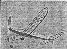
Earl wasted many exposures before getting this swell shot. But
it was well worth the time spent - for here we seethe "Hurricane" coming in for -a "eat, long - glide landing.
|
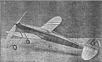
Sleek-- and how ! What's more, that color scheme makes the
ship's lines even more flashing. When putting the finishing touches on your craft, refer back
to this photo so you can get your tapering fuselage-stripe just the same as shown here. And
those diagonal wing - markings go well in making the job stand out better at high altitude.
|
BILL OF MATERIALS
(Plans on following four- pages)
Nine strips 1/8" sq. by 36" medium balsa for fuselage stringers and
cross-braces;
Eight strips 3/32" sq. by 36" medium balsa, for fuselage and
cross-braces;
Two strips 1/16" sq. by 36" medium balsa for wing stiffeners;
Two strips 1/8" by 3/16" by 36" medium balsa for wing leading edge;
One strip 1/16" by 1/8" by 36" medium balsa, for wing trailing edge;
One sheet 1/16" by 2" by 36" soft balsa for ribs, formers, and covering;
One sheet 1/8" by 2" by 18" soft balsa for rudder trailing edge and
covering;
One block 1" by 1-1/2" by 12" very hard balsa for prop;
One pair wheels, washers, 20' brown rubber, 1/16" and .040 music wire,
glue,
dope, tissue, rubber tubing, hardwood dowel, pins, sandpaper, etc.
Scanned from July 1940
Flying Aces


[ Home ] [ Previous Plan Pages ] [ Special
Things ] [ Earl Stahl Plans ]