The Plan Page
[ Home ] [ Previous Plan Pages ]
[ Special Things ] [ Earl Stahl Plans ]
Earl Stahl's
"GYPSY" OUTDOOR MODEL
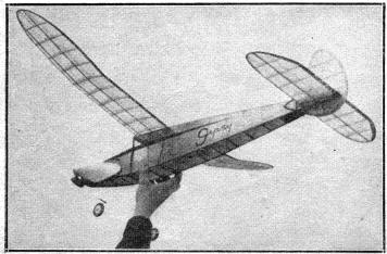
A cleaned up version of the 1939 Wakefield entry, this job flies even better.
THE FINEST characteristics a model can possess are: ease of construction, a great degree of stability, an efficient high climb, and the ability to soar when the power is exhausted. The "Gypsy" has repeatedly demonstrated that it has these qualities. Our first model of this design was actually flown many hundreds of times. For nearly a year it - was tested in all kinds of weather, and minor changes and readjustments were made until the performance was consistently good. It was this model that gained a place for the author on the 1939 United States Wakefield team. At the Wakefield finals, however, the intense heat caused the huge rubber motor to snap when only partially wound. The model was nearly disintegrated by the broken strands of rubber, but Ted Just, who was flying the ship by proxy, managed to repair what remained and made one shore official flight. But that is another story.
Shown in the photos is an improved version of the original model. During the past season it was used in numerous contests with good results. On a recent test flight it soared out of sight.
Because of the "Gypsy's" large size, it has been necessary to make most of the plans one-half scale, so the first job is to make actual size drawings of the fuselage, wing, and tail surfaces. This will be a simple task since it will only be necessary to increase each dimension two times. In reproducing the fuselage, care should be exercised to make the angle of the top of the fuselage exactly right since the wing's correct incidence depends on your accuracy. Draw 1/2" squares on your plan and duplicate the wing and stabilizer tips as well as the rudder.
FUSELAGE CONSTRUCTION
OUR FUSELAGE is subject to considerable stress and punishment, so much strength without excessive weight is required. Select four hard 1/8 " sq. strips for the longerons, which should be of similar strength and weight. Work directly over the full size plan and make two fuselage sides, one atop the other to insure that they will be identical. It should be noted that the tail piece to which the rudder and stabilizer are attached is made integral with the fuselage and then when the entire structure is completed it can be cut off. Pins placed at frequent intervals will help keep the longerons and cross-pieces in place until the cement has set. Place the two sides in position over the top view and join them with 1/8" sq. spacers and the three F-4 formers which are cut from 1/8" sheet. Check continually for correct alignment.
Full size formers are shown on the plan and they are cut from 1/8 " sheet. Cement formers F-1 and F-3 to place and then attach the 3/32" sq. fairing strips. Short pieces of 3/32" sq. are cemented between the fairing strips to complete the nose as shown by section F-2. Shaded areas at the front and rear of the fuselage are "filled in" with 1/8" sheet for added strength, and to provide a place to hold the model while the powerful motor is being wound. Thin aluminum plates are cemented securely to the sheet balsa in the rear; they serve to cradle the hardwood dowel pin which is fitted through the fuselage to hold the rubber motor.
Construction of the landing gear is simple. A single length of 1/16" diameter music wire is required. Use heavy pliers and bend to the shape and size shown. With strong silk thread bind the landing gear to the fuselage structure and then apply several coats of cement. Wheels are made from laminated 1/8" sheet of a very hard variety. Cement bearings or washers to the wheels so that they will revolve freely and accurately. Washers soldered to the wire struts will hold the wheels in place.
WING, TAIL, AND PROPELLER
IF A FULL SIZE plan has been prepared, construction of the wing can be started. It is built in halves. Ribs are cut from soft grade 1/16" sheet. Be very accurate and make them as shown on the plan. Spars are hard balsa and they must fit accurately into the notches in the ribs. The tip outlines are cut from 1/8" sheet. Work directly over the plan and assemble the various parts using pins to hold them in place until the cement has hardened.
As shown on the plan, the outer section of each wing half is elevated to the extent of 2-1/4 " at the tip. To raise the tip it will be necessary to cut the upper spars at the sixth rib, and to crack the lower ones. Thoroughly re-cement the spars and then join the wing halves so the dihedral at each tip will be 5-3/4".
Construction of the stabilizer is practically identical to that of the wing. Nine ribs cut from 1/16" sheet balsa are required. Taper the 1/8" by 3/8" trailing edge and then cut the tip pieces from 1/8" sheet. Assemble the parts over the plans using hard stock of the correct size for the leading edge and the spars. When dry, remove from the work board and trim and sand to the finished shape.
A thin, streamlined rudder is used. First, make a flat structure using 1/8" sheet for the outline pieces and 1/8" sq. for the spar and ribs. When this structure is completed, it is lifted from the plan and 1/16" by 1/8" strips are cemented to the sides of the ribs. The ribs are then cut to a streamline shape and the leading and trailing edges are cut to blend with the ribs.
FOLDING MECHANISM
A ONE BLADE folding propeller is used on the "Gypsy." Select a hard block 8" by 2" by 1-5/8" and cut out the blank as indicated on the plan. Carve a right hand prop, About 1/8" of undercamber should be cut and sanded into the back face and the blade should be thinned as much as possible while still retaining the required strength. Thoroughly sand the prop and then apply several coats of clear dope with light sanding between each to obtain a smooth, hard finish.
The hub is made from a separate block 2" by 3/4 " by 5/16" and it should be of very hard balsa or even white pine. Drill the hole for the propeller shaft and then finish to the shape indicated.
There are numerous different methods for folding the prop blades, but we like the one shown on the plan best. Four fittings are made from 1/32" sheet brass and they are securely cemented to the blade and hub. A short length of .040 music wire is used for a hinge. Regardless of the type of folder used, it should be remembered that the blade must be held rigid yet it must be free enough to permit the blade to snap back the instant the power is exhausted. Many of the model supply houses now stock folding propeller gadgets that, are both practical and reliable, and they cost but a few cents.
A counter-weight is made by pouring molten lead in a tube made by wrapping paper about a pencil or similar round object. The .040 music wire is inserted in the liquid metal before it sets. With thread, neatly bind the wire to the prop hub. The unit is made to balance by reducing the weight to the proper size.
For the nose plug a hard balsa block is required. First, drill the hole for the prop shaft and then shape the plug so it will blend neatly with the fuselage. A piece of pine is cemented to the back of the nose block and it should fit accurately within the fuselage. Small brass plates, as shown, are cemented over the prop shaft hole to fix the line of thrust. Similar plates are used on the propeller also.
The various parts of the propeller unit should now be assembled. From 1/16" diameter music wire start to bend the back of the prop shaft, Slip the nose plug, several washers, and the propeller on in the order given. Bend a loop for a winding hook on t he shaft and then bend the end so it will fit into the hub. The wood screw at the back of the nose plug is placed in such a position as to stop the propeller blade at the most favorable position along the nose. The small spring at the front of the unit is shaped from .034 music wire. A small rubber band wrapped around the shaft and catch will keep the loop from opening when the motor is tightly wound. Once the model is complete, adjust the wood screw so the catch on the shaft will pass when the motor is wound, and so it will be stopped when only a few turns remain.
COVER, ASSEMBLY, AND FLYING
MUCH OF THE MODEL'S beauty depends on a neat, attractive covering job, so the entire structure should be sanded thoroughly. Cellophane is cemented to the side windows (the windshield is celluloid) and the individual units are covered with tissue, using banana oil for the adhesive. When covering, put adhesive on the extreme outlines of the frames only. If any wrinkles are present, they can be removed more successfully if this procedure is followed. One exception should be noted, however, on the under-surface of the wing the paper should be attached to each rib and spar to preserve the airfoils' shape. Water spray the parts and pin them to a flat surface to prevent warping. The entire model should be given one or two coats of dope.
Assembly of the various parts completes the construction. Attach the wing to the fuselage with a piece of 3/16" flat rubber. The removable tail piece is held to the body by rubber bands wrapped around the bamboo splints and the dowel. Slip the stabilizer through the slot in the tail piece and cement it fast after checking for correct alignment. The front of the rudder is off-set about 1/16" so the model will glide to the right.
Use 18 or 20 strands of 3/16" flat, brown rubber, 36" long for power. The rubber strands should be well lubricated, but the excess lube should be wiped off to keep it from splashing on the covering. Hook one end of the motor to the prop shaft and then bind the shaft with a small piece of rubber to keep the strands in place. Drop the other end of the motor through the fuselage and slip the dowel pin in place to hold the strands.
The degree of success of any flying model is usually determined by the builder's ability to make proper adjustments. Approximate position of the wing is shown, and if the plans were closely followed, the wing and stabilizer angles will be correct. The descent from a hand glide should be long and smooth, but a tendency to dive or stall can be corrected by sliding the wing forward or backward.
For best performance the "Gypsy" should fly and glide in right-hand circles. Confine all adjustments at first to the glide and then once it is good, correct any improper flight attitudes by off-setting the thrust line. If a tendency to mush or stall is apparent, a sliver of balsa between the nose plug and fuselage causing it to pull down, will probably correct it. Right or left thrust, as required, will help make the model circle as desired while under power. Once the adjustments seem satisfactory, cement any correction blocks in place.
Use a mechanical winder for maximum performance. And if the motor is stretched about two and one half times normal length before starting to wind, the rubber strands can safely be wound 800 to 900 turns.
BILL OF MATERIALS
11 pieces 1/8" by 1/8" by 36" hard balsa f or longerons, spars, etc.
6 pieces 3/32" by 3/32" by 36" for spars, fuselage fairings
2 pieces 1/16" by 1/8 by 36" for rudder
2 pieces 1/16" by 1/16" by 36" for stabilizer spars
1 sheet 1/8" by 2" by 36" for tips, fuselage, "fill-in," etc.
2 pieces 1/8" by 3/8" by 36" for trailing edges
2 sheets 1/16" by 2" by 36" for ribs, formers, etc.
1 block 8" by 2" by 15/8" for propeller
1 piece 2" by 3/4" by 5/16" for propeller hub
1 length each .040; 1/16" dia. wire 60 ft. 3/16" flat, brown contest rubber
2 sheets, colored tissue, plus dopes, celluloid, cellophane, block for nose,
brass for hinges, etc., etc.
THE END
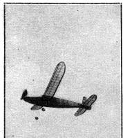
Here’s the contest - winning ship in full flight

Flights of several minutes are not uncommon with the "Gypsy."
Scanned from September 1942
Flying Aces
![]()
![]()
![]()
![]()
[ Home ] [ Previous Plan Pages ] [ Special
Things ] [ Earl Stahl Plans ]