Finished model - if you select wood carefully - weighs under 4 ozs. Glide is as smooth
and as buoyant as Earl's old time rubber-powered jobs.
The Plan Page
[ Home ] [ Previous Plan Pages ]
[ Special Things ] [ Earl Stahl Plans ]
gt-hunter1@home.com
Finished model - if you select wood carefully - weighs under 4
ozs. Glide is as smooth
and as buoyant as Earl's old time rubber-powered jobs.
Emeraude
by EARL STAHL
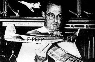
For years old timers have been asking for more flying scales by the old master. MAN is happy to present his latest, the French Piel Emeraude, for an .02.
France's encouraging attitude towards the construction and operation of amateur built aircraft makes her a world leader in this challenging and rewarding activity. Many hundreds of fine French home‑built light planes are in use by flying clubs and individuals.
One of the most popular home‑builts is the trim, fine performing Piel "Emeraude." A two‑seater of moderate cost to construct and operate, it is ideal for training and sport. Many are already flying in Europe, and several are nearing completion in the United States and Canada. Like most foreign light planes, construction is basically wood. The spruce and plywood structure, somewhat similar to our model, is fabric covered.
|
|
|
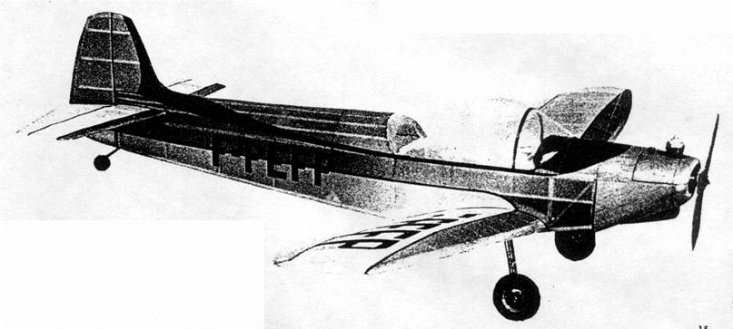
Several versions of the Emeraude have appeared, and all are fitted with American Continental engines of 65 to 90 horsepower. The model CP‑301 with the larger engine cruises at 118 mph, and yet it has low speed performance which enables it to operate from the typical small, grass runway French flying fields.
Our free‑flight model captures not only the graceful lines, but also the good flying qualities of the real craft. An effort has been made to keep model weight low without sacrifice of strength or appearance. The light wing loading resulting from the 3.9 ounce total weight of the original model produced a nimble craft capable of gliding as smooth and slow as the old time buoyant rubber‑powered models.
Standard construction techniques are used throughout, so the builder will find the model easy to reproduce. Needless to say the full‑size plans will simplify the job. Study the plans and text thoroughly before starting so each construction detail will be understood before it is encountered.
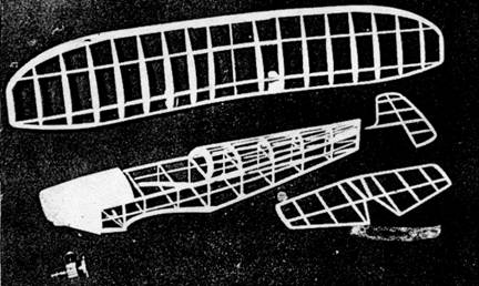
CONSTRUCTION
Fuselage: Primary frame is assembled first; it is shown lightly shaded on the plan. Build two side frames, one atop the other, working directly over the plan. Notice that these side frames extend from the back of the nose block to the rudder. Both longerons and uprights are 1/8" x 1/8" hard balsa. The curved sheet balsa member where the wing joins the fuselage is part of the primary frame, and it serves to locate the wing position. When dry, the side frames are separated, and positioned inverted over the top view. Cross members of 1/8" x 1/8" balsa join the side frames, but only those from station F‑3 aft are installed at this time. Check the structure frequently to assure proper alignment.
Fuselage formers are cut from 1/16" sheet balsa, except those in the region of the engine which are 1/16" plywood as specified on the plan. Formers F‑2 and F-2B are the engine mount, and should be glued together at this time. Drill the engine mounting holes, and cement nuts to the back side of the holes, so the engine can later be installed or removed with ease. Now attach this engine mount assembly to the primary frame observing that it fits behind the vertical member of the side frame, and is notched to fit over the top and bottom longerons. Incidentally, the top and bottom longerons of the side frames must be cracked at station F‑3 to allow the forward ends to be drawn together. Next cement the remaining formers to their respective positions. Hard grade 1/16" x 1/16" stringers are fitted into the notches of the formers, and are cemented fast. The single stringer on each side of the primary frame is cemented directly to it. Observe the 1/16" sheet balsa stabilizer mounts atop the longeron between formers F‑10 and F‑11; measure the drawing to get the exact front and back height of these parts since they determine the incidence of the stabilizer.
To enhance the model's strength, and meanwhile simulate the metal cowling of the real craft, shaded portions of the nose are covered with 1/32" sheet balsa. A number of pieces will be required, and stock sufficiently wide to allow joints to fall only over formers and stringers should be used. Once cut to fit, the sheet covering should be securely cemented to the entire adjacent frame. Pins and rubber bands be found helpful to hold the covering in place until the cement hardens. Gussets F‑12 of hard 1/16" sheet balsa are fitted into the engine compartment between F‑1 and F‑2, and adjacent to the inside of the primary frame. Purpose of these gussets is to strengthen the nose, and to help confine spilled fuel from other parts of the structure. Two 1/8" diameter holes should be provided at the lower back of the engine compartment to drain spilled fuel. The entire inside of the engine compartment should be treated with several coats of fuelproof dope to properly protect the structure.
The section of cowl removable for access to the engine should, of course, be built right along with the rest of the nose. Make the cowl front from laminations of 1/8" sheet balsa as shown. The completed cowl is held to the nose of the model by two triple zero size dress snaps which are cemented into slight depressions carved out for the purpose, and by a 1/8" diameter dowel which enters a hole in F‑2. Cut outs for the engine cylinder and needle valve are made by cutting the skin and understructure away as is required.
Rudder and stabilizer: Construct in a similar manner. The outline pieces are cut from 3/32" sheet balsa to the width and shape shown. Pin the outline pieces over the drawing, and then place the 3/32 x 3/32" spars ribs of the same material are fitted next. When dry, lift the frames from the jig and cement 1/16" x 3/32" soft strips over each side of each rib. Finally trim and sand the ribs and leading and trailing edges to the shape of the typical tail rib, shown on the plan.
Wing; The builder has the option of attaching the wing permanently with cement, or making it removable as on the original. A removable wing and landing gear assembly has the advantage of being more easily transported and stored. Further in the event of a collision the wing usually becomes detached, and this tends to reduce model damage. In either case the wing is built the same. Cut the ribs from medium 1/16" sheet balsa. Carefully sand each rib to exact shape, and then cut the spar notches with accuracy. Leading edges are 1/8" x 1/4" strips, and leading edge tip pieces are cut from 1/4" sheet balsa. Trailing edge tip pieces are likewise cut from sheet balsa, but from 1/8" thick material. Spars are 1/8" x 1/8" hard balsa, and the trailing edge is medium grade 1/8" x 3/8" balsa. Assemble the right and left wing panels from W‑1 outboard; do not, however, install ribs W‑1 at this time. Once the cement has set raise the tip of each outer panel 1-3/4", and then complete the center section by installing the leading and trailing edge and the spars. Strengthen the whole assembly by securely cementing gussets W‑6 through W‑9 to place. Finally, install the several parts of the W‑1 ribs. A small balsa block is used to fair the under surface of the wing leading edge to the adjacent fuselage. An additional fairing strip, 3/32" x 3/32" is placed chordwise at the bottom of the center of the wing.
A durable, realistic landing gear can be made for your Emeraude in this manner: Bend a right and left strut to the size and shape shown on the drawing from .050" music wire. Then using a needle and thread sew these struts to the W‑7 spar gusset and the W‑1 ribs. Note that the W‑7 gusset has two small holes which allow the landing gear wire to pass through for contact with rib W‑1. To complete the attachment of wire to the frame, coat the thread and adjacent wood areas with several applications of cement.
For lightness balsa wheels are recommended. These can easily be made from laminated discs of hard balsa. Cement flat washers to each side of the wheels to provide a suitable bearing surface for smooth, accurate turning.
Covering: Frames should be carefully sanded to remove all flaws and roughness. To help produce the best quality covering job the author always sands fuselage formers between the stringers to a scalloped shape so the covering will only contact the stringers. This is accomplished by using several different appropriate diameter dowels wrapped with sand paper. Formers W‑7 through W‑10 should be scalloped in this manner.
Either colored tissue or light weight Silkspan may be used for covering. The latter is probably easier to use, but the author likes best the appearance of the colored tissue job. Use thinned clear dope for adhesive. If colored tissue is used, numerous small pieces will be required for curved parts of the fuselage, and for the wing tips to help avoid wrinkles. Sheet balsa parts such as the nose should be covered in the same way as the frames.
Assembly: If the plans have been followed carefully, wing and stabilizer incidence will be correct when the parts are slipped to place. It will be necessary to remove a portion of former F‑11 to allow entry of the stabilizer which is then cemented fast; once the stabilizer is in place, the removed section of F‑11 can be replaced. Cement the rudder to place with about 1/32" offset for a right hand turn. As noted before, several small rubber bands looped over the fuselage dowels and under the wing will join these parts. Several applications of clear, fuelproof dope should be brushed on the entire model.
The plastic canopy is an outstanding part of the model, and it is formed fairly easily. First make a complete canopy from pine or even balsa; shape it accurately and smoothly since any flaws in the form will be reproduced in the finished product. To simplify the stretching operation, the finished form should be solidly mounted on a base smaller than the form itself so the plastic can be drawn well below it without restriction. Now heat a generous size piece of soft plastic in boiling water or over a hot plate until it becomes pliable, and then using every available hand (at least four with gloves!) quickly stretch the plastic down over the form. If the first attempt is not wholly satisfactory, simply reheat and try again. Any blemishes in the plastic can be removed by polishing with a very mild rubbing compound. Trim the canopy to its exact shape, and then cement it to place. The structural member of the real canopy can be simulated with black tissue or paint.
A scale model is really "made" by the quality and amount of detail incorporated in it. Since weight is such an important consideration, this must be accomplished with extreme care. To produce an authentic looking landing gear, a realistic fairing is required. For the original we found a light, flexible strip of plastic insulating material which was slid over the wire leg. Wheels are painted, and then held to the axles by washers soldered to the ends. Carburetor air intake, tail wheel, etc. can be made from scrap materials. If colored tissue has been used for the covering, control surface outlines, flap, etc. can be represented by narrow strips of black tissue doped to the covering. License numbers may be cut from colored tissue, or the popular decals may be preferred.
Flying: To assure maximum success in test flying, a careful approach to the problem must be made, Before attempting any flights reexamine the model for undesirable warped surfaces or misaligned parts. The model should balance at a point about 1-3/8" aft of the center section leading edge; in the very likely event that It does not, add weight to the nose or tail to position the center of gravity correctly. Make hand launched glide tests over tall, soft, grass so landings will be cushioned in case further weight adjustment is required to get a smooth descent. Glides should be almost straight with only a suggestion of right turn ‑ a left turn is not likely to be acceptable. Once the glide is satisfactory try minimum power flights. Resort to all the tricks ‑ reduced power, short engine run, prop backwards, etc. ‑ to permit study of the model's flying characteristics before proceeding further. If possible, concentrate on the power‑off performance, seeking a smooth wide circling glide to the right. With the glide okay adjust the power flight by tilting the thrust line. A little right thrust was used on the original, and this was achieved by slipping folded aluminum foil between the left side of the engine and the mount. As performance improves and confidence is gained, increase the engine power making any further thrust line adjustments dictated. You have a considerable investment in effort and time in your Emeraude so handle it thoughtfully, and it will reward you with much flying enjoyment.
Scanned from April, 1960
Model Airplane News
![]()
![]()
[ Home ] [ Previous Plan Pages ] [ Special
Things ] [ Earl Stahl Plans ]