 Square fuselage and tail surfaces are easy to build |
 The most realistic model you will ever build |
The Plan Page
[ Home ] [ Previous Plan Pages ]
[ Special Things ] [ Earl Stahl Plans ]
gt-hunter1@home.com
Square fuselage and tail surfaces are easy to build |
The most realistic model you will ever build |
FOKKER D-8
Flies Again
A Realistic Gas
Model of a Famous Fighter
That Performs Like a Contest Plane
By EARL STAHL
PART 2
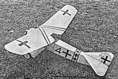
 Its interesting details give fine appearance |
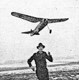 A steady exhibition or contest flier |
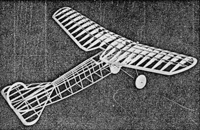 The frame is light and carefully designed |
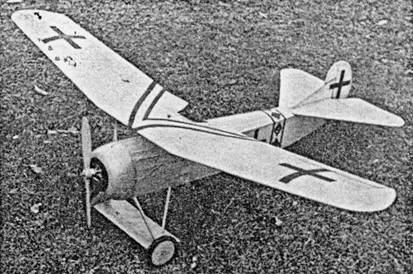
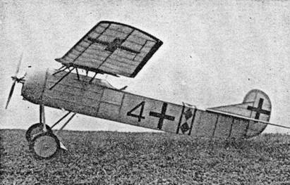 On the field it looks like the full scale plane |
IN THIS, the second and concluding part, plans and instructions for completing the flying scale Fokker D‑8 are given. If you wish to begin construction of this realistic, fine flying model, we suggest you get a copy of last month's MODEL AIRPLANE NEWS and catch up with the job. For those who are ready to continue, the first step is to "scale‑up" to actual size the various parts.
Wing
Begin constructing the wing by cutting the various ribs from 1/16" sheet balsa. Two of each type are required. Rib No. 1‑B is identical to No. 1 except that the area between the spars is removed; No. 1‑C has the trailing edge removed to extent indicated by the broken lines. Sand all ribs smooth and cut notches for spars with the exception of the 1/8" square upper spar; all others are 1/8" x 1/4".
Assemble the wing in three parts: Two outer panels and center section. Taper the 1/4" x 3/4" trailing edge pieces and pin them over the plan. Use pins or brads to hold ribs in place and then attach the 1/4" square leading edge. Select hard 1/8" x 1/4" stock for the spars but only cement lower ones to place. The tip pieces are cut from 1/4" sheet. When assembling the center section, it will be necessary to cut the curved pieces, where the wing is cut away, from 1/4" sheet. The short piece extending beyond the 1‑C ribs is 1/2" x 3/8".
Before joining the three parts, the ends of the leading and trailing edges are cut to their exact length. Now pin the center section to the work bench or other level surface; then elevate the tips of the outer panels to the extent of 4". Accurately join the various members and cement thoroughly. Add upper spars and then cut dihedral reinforcements from very hard 1/8" sheet. Fit these accurately between the spars and ribs No. 1 and No. 2. The several parts of ribs 1‑B are next cemented to place. Recement all joints for added strength. Cut and sand the leading edge and tips to final shape and go over the entire wing structure with fine sandpaper, to remove all roughness, so a neat covering job can be made.
Four wing hooks are bent to shape shown, from .040 wire. These are attached to the wing structure at a distance apart so they will fit snug against the outside of the wing rests. Hold hooks in place by sewing right through the dihedral reinforcement and then around the spars and hooks. Apply several coats of cement.
Tail Surfaces
Construction of the tail surfaces is so easy that very few instructions are required. The rudder plan is shown on the side view; enlarge both the stabilizer and rudder plan to full scale and assemble the parts directly over these plans. The rounded outlines of the rudder are cut from 1/4" sheet as are the stabilizer tips. Leading edges of each are 1/4" square and the ribs are 1/16" x 1/4" strips. Give all joints several applications of cement to help prevent warping and when dry, cut and sandpaper to finished shape.
Covering
Our model of the Fokker D‑8 was covered with both silk and Silkspan. Silk is the finest covering material for gas planes because of its great strength. light weight and attractive appearance; the only drawback is cost. Because the fuselage is subject to so much punishment, we covered this part with silk; the wing and tail surfaces. were covered with light Silkspan. Use thin cement for adhesive and cover the model in the conventional manner. When covering the undersurface of the wing, be careful to stick the covering to all of the spars and ribs to preserve the airfoil's shape. Shrink the covering with water and then apply one or two coats of clear dope.
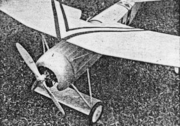
The smaller details should be completed before the model is colored. As explained before, the cabane and landing gear struts are made streamline by strips of soft 1/16" x 3/16" balsa which are attached by spiral wrappings of tissue or silk strips. But before this is done, the four small hooks illustrated below the cabane strut details are soldered to the wing struts. The fourth strut on each side of the wing mount is a false strut, placed there for scale appearance only. Since this strut carries none of the stress, it should be in de from soft 3/32" x 1/4" cut streamline and then lightly cemented to place. The wing mount without this strut is sufficiently sturdy yet it is also flexible enough to absorb more punishment without damage, than a rigid mount.
After the model has been flown for sometime it may be necessary to repair or replace these two struts, but that is certainly easier than repairing the whole mount or even the wing. Four small blocks are cemented to the pine wing rests to keep the wing from sliding: use soft balsa so they will break off in the event of an accident and thus protect the wing from serious damage. Typical on all Fokker war planes was the small wing between the wheels. This can easily be reproduced but is not recommended when flying the model since it would probably "trip it" every time it lands.
Color of the model shown in the photos is flaming red‑orange; this is especially striking with black trim. If possible spray the colored dope on to the covered surfaces: thin the dope and apply two coats. Decorations can be painted on, using masking tape for a neat job, or they can be cut from black tissue and doped to place. Paint tires, tail skid, inside of cowl, etc., black.
Now let's put the parts together to see how she looks. Wheels are held to place by washers soldered to the axles place a washer at both sides of the wheels so they will turn freely. The stabilizer is cemented to place over the incidence strips and rudder is cemented on next. Off‑set the rudder a bit so the model will glide to the right. Check and recheck for correct alignment.
Some builders may not like the idea of permanently attaching the tail surfaces and in this case it will be all right to make them removable, provided some method is devised to make adjustment secure. Bolt the engine mounts to the engine bulkhead with a 1/16" thick washer between the top of the mount and the bulkhead to give the engine the required amount of negative thrust. If a metal cowling is being used, it should be mounted, by small wood screws, to several small balsa blocks, which are cemented to the firewall. The engine unit is held to the fuselage by four small rubber bands wrapped about the hooks on the cowling and about the front wing and landing gear struts. Set the wing on the pine rests and secure its position by wrapping small rubber bands around the hooks.
Well, there she is‑attractive isn't it?
Ignition
To install the ignition system it will be necessary to remove the engine unit. Details of the battery box for intermediate size cells are given. Use the finest grade stranded wire available for wiring, and solder all connections. Broken lines on the side view show the approximate position of the various parts. On the test ship the coil was attached by adhesive tape to a piece of balsa 1/8" x 1" x 3", cemented to the right side of the fuselage structure. The tinier was mounted conveniently in the cockpit and the battery box was permanently attached to the left side of the fuselage just forward of the cockpit. Determine the batteries' correct position by changing them until the plane rests in a level position when held under the center wing spar. The condenser is attached to the engine mount. Now install fresh batteries and your Fokker D‑8 is ready to fly.
Flying
First flight tests should be hand glides. Turn the propeller to horizontal and launch the plane at four or five feet of altitude. It should make a steady, smooth glide to the ground but, in the event it stalls or glides too steeply, the batteries will have to be shifted.
Once your D‑8 glides well, start the engine and make it run as slowly as possible without danger of stopping. Set the timer for 12 to 15 seconds and hand launch. Observe the flight carefully, making necessary corrections before the next trial. Make all adjustments to favor the glide and then off‑set the thrust line to make the power flight as desired. Right or left thrust will control the amount of circle while under power and if it has a tendency to mush or stall, increase the negative thrust a slight amount. While it was unnecessary on the test model, a small aluminum tab can be attached to the rudder to help adjust the circles. Good luck to you!
Scanned from July 1941
Model Airplane News
![]()
![]()
![]()
[ Home ] [ Previous Plan Pages ] [ Special
Things ] [ Earl Stahl Plans ]