|
|
|

A Miniature Flying "Cadet"
A Realistic Flying Scale Model With
Proportions
That Give It Contest Performance
BY EARL STAHL
The Plan Page
[ Home ] [ Previous Plan Pages ]
[ Special Things ] [ Earl Stahl Plans ]
gt-hunter1@home.com
|
|
|
A Miniature Flying "Cadet"
A Realistic Flying Scale Model With
Proportions
That Give It Contest Performance
BY EARL STAHL
UNCLE SAM has recognized that one of the greatest assets to the aerial defense of our nation is to have a vast store of trained flyers. The Civilian Pilots Training Program, while of a non‑military nature, is expected to supply, at a comparatively low cost, thousands of potential military aviators: 100,000 of whom are said to be required to man the great number of fighting craft now under construction.
Interstate's new lightplane, the "Cadet," was designed specifically for the requirements of training planes for this program. This two‑passenger sport‑trainer follows conventional lightplane practice and incorporates features of design and construction to improve performance and facilitate manufacture and maintenance. Powered by a four‑cylinder Continental engine of 65 h.p., it zips along at a maximum speed of 109 m.p.h. A non‑stop flight of 375 miles is possible while averaging 100 m.p.h. When it is necessary to land the "Cadet" floats to the runway at a mere 36 m.p.h.
Aerodynamically and structurally, the Cadet is ideal for modeling. Unlike most lightplanes, it has a rather long fuselage as compared to the wing; the nose is long enough to create proper balance. Further, a large propeller can be used without lengthening the landing gear. Because of the plane's simple yet attractive design, it is not difficult to construct an accurate, rugged model with a superior flight performance from the plans which accompany this article.
Following is the recommended procedure of construction.
Fuselage
Properly join the plans together so construction can be started. A rectangular frame is the backbone of the fuselage, it is shown lightly shaded on the plan. Two sides are built from medium ‑ grade 3/32" square balsa, one atop the other to insure identify. When the cement has dried, the two sides are inverted over the top view; pin them into position and cement the 3/32" square crosspieces to place. being careful the entire structure is correctly aligned. It will be necessary to crack the longerons in order that they can be pulled into position at the front. Cut the formers of sections A‑A, B‑B and former No. F‑3 from 1/16" sheet, and now, if the basic structure is dry, it should be removed from the work board and the formers should he attached to their correct places. The wing center section is construction atop the fuselage; make this very accurate since the wing's correct placement is determined by its position. Since the stringers are merely fairing strips, they should be of soft balsa. As shown by a view of a typical fuselage cross‑section, the stringers are cemented directly to the underframe, except where there are formers, of course.
To effectively represent the metal engine cowling of the real ship, a portion of the nose is covered with thin balsa sheet and the remaining portion is "filled‑in" with scraps of soft balsa. The section above the main longerons call be covered with 1/32" sheet since the curve is uniform. Use soft balsa and cement it to the adjacent frame. Below this covering, separate pieces of very soft 1/8" sheet are fitted snugly between the formers and stringers and when dry the "filled‑in" areas are cut to the correct shape. The extreme front of the nose is made removable to permit the rubber motor to be stretched for winding. Roughly cut the nose block to shape and then lightly cement to the fuselage and sand the entire front smooth and uniform. Remove the nose block and cement a piece of 1/8" thick stock to the back so it will fit to the opening in section A‑A.
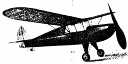
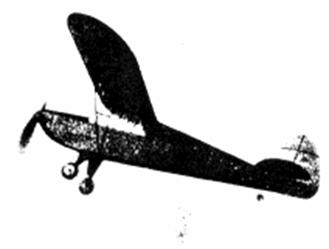 It's just like a large ship in flight. |
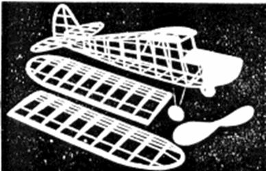 The structure is strong and light |
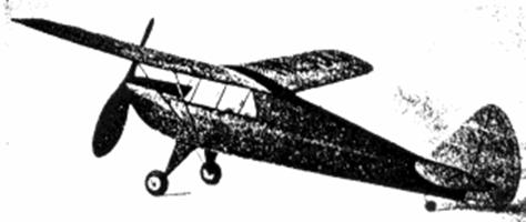
Stability from
high wing; efficiency from large prop
Landing gear struts are .034 music wire the size of each strut being indicated on the plan. Once the struts are formed, they are attached to the fuselage by thread bindings. Front and back struts should be joined with solder. 1/16" sheet is used to fill the space between the struts; do not attach the balsa struts, however, until the fuselage has been covered. Wheels may be purchased or they can be made from discs of 1/8" sheet that have been laminated together.
Tail Surfaces
Since any excessive weight behind the center of gravity must be balanced by additional weight in the nose, the tail surfaces must be kept light. Both stabilizer and rudder are constructed in a similar manner. In the interest of greater strength the stabilizer is built in one piece. Outlines are cut from 1/16" sheet, ribs are 1/16" square and spare are 1/16" x 1/8" strips. When dry, the frames are removed from the plan and very soft pieces of 1/16" square cemented to both sides of the ribs. Ribs are cut streamlined when the cement has dried. Cut and sand the surfaces to their final shape.
Wing
Because of the limited space, only one half of the wing could be reproduced on the plan, so make a full‑sized layout on a large sheet of paper and work can be done directly on it, Taper and sand the trailing edges before pinning them into position over the plan. With the exception of the two 1/16" thick end ribs, the wing ribs should be cut from 1/32" sheet. Pin the ribs to their respective positions and then attach the leading edges and spars. Assemble the tip pieces, which are cut from 1/8" sheet and then cement the tips to place. Once the Ieading edges and tips are cut and sanded to their proper shape, the wing frames are completed.
Propeller
For best flight performance the model must be equipped with an efficient propeller. Select a hard block 8" x 1‑1/2" x 1" for the prop. Drill the tiny hole for the propeller shaft. then cut the blank as indicated. A right‑hand prop is carved: thin the blades as much as possible while still retaining the required strength. Cut the blades to a nice smooth shape ‑ take your time and do a good job. The spinner is made by cementing small blocks to the sides of the hub; when dry they are cut to the desired shape. Several coats of light dope, if lightly sanded between coats, will give a smooth finish. Some kind of free‑wheel gadget should be used to permit the prop to spin in the glide. Cement a washer to the back of the prop, too.
Covering
A neat, attractive covering job is a necessity for any fine flying scale model. Colored tissue is used and since this is a commercial plane, most any color combination will be correct. Our test model of the Cadet was colored red and blue with black trim. Every bit of the structure should be lightly but thoroughly sanded to properly prepare for a neat job. Cement cellophane side windows to place before starting to cover the fuselage, Bear in mind that only the longerons and stringers should touch the covering; the use of numerous small pieces of tissue on curved parts will help avoid wrinkles. Use only enough banana oil adhesive to stick the extremities of the area being covered and lap the individual pieces neatly. The balsa cowling and other similar parts are tissue‑covered, too. Use several separate pieces of tissue on the wing tips, etc, Once covered, all parts are lightly sprayed with water to tighten the tissue. The tail surfaces and wing should he pinned to a flat surface to prevent warping. Clear dope is not applied to the covering until later,
Assembly
The various parts are now assembled. A half‑windshield pattern is given on the plan; cut a complete paper pattern to make certain that it will fit your model before cutting one from celluloid. Avoid cement smears when attaching the windshield. Attach the stabilizer to its position on the top longerons. Off‑set the rudder a bit to counteract prop torque: it should be perpendicular to the stabilizer. The balsa landing gear struts which were made previously should be attached. On the original model they were secured by covering both wire and wood with light silk which was then doped fast. Cover the struts with tissue to match the fuselage. The struts between the landing gear legs are made from rounded bamboo splints. Bearings should be cemented to the wheels so they will revolve smoothly, Color the wheels and tires. Wheels are held to place by a drop of solder at the end of the axles. Attach the wings. This will be an easy matter since the exact position and angle have already been determined. Tips should be elevated 1‑3/8" to give the proper angle of dihedral. A coat of clear dope can now be brushed on the entire model. Do this in a dry room to prevent "blushing"; exercise caution to avoid warping of the flying surfaces.
Addition of many of the more minor details will aid greatly in making the Cadet's appearance more snappy. License numbers, fuselage stripes and similar items are cut from contrasting tissue. Ailerons, elevators, rudder, a door, etc., are effectively represented by thin strips of black tissue. Full‑size wing struts are shown in broken lines on the wing plan; they are 1/16" thick and they are of streamline cross‑section. Struts, propeller and other exposed wood parts are color doped. Air intake openings in the cowl, exhausts, a tail wheel and many other details can be found on photos of the real ship; they can be added to the model without impairing the flight qualities.
The hole in the prop shaft through which the prop shaft passes should he fitted with washers at both sides to fix the line of thrust ‑ ‑ about one degree of right thrust should prove advantageous, Bend the prop shaft from .034 music wire. The nose block, several washers and the propeller are slipped on in the order given. A loop at the end of the shaft provides a place to attach a mechanical winder.
About 10 strands (5 loops) of 1/8" brown rubber will be required for motive power, Measure the strands to the correct length and then attach them to the loop on the prop shaft. Drop the rubber through the fuselage and slip the bamboo pin through the fuselage so as to attach them in the rear.
Flying
One of the most important factors in obtaining excellent flights from any flying scale model is patience. A well‑built model, if properly handled, will provide countless realistic flights with little or no damage to the plane itself, If the plans were closely followed, the model should balance and fly with but little adjustment. Add weight to the nose or tail, as the case may be, to make the Cadet glide well, and then adjust the thrust line to correct the power flight. A small sliver of wood between the nose block and fuselage, tilting the thrust line down at a slight angle, will eliminate a tendency to stall; while right or left thrust will make the model turn as desired. Use a mechanical winder for long flights. Stretch the rubber strands about 2‑1/2 times normal length and store up power.
Our original model was well tested and proved to be a splendid flyer. When the motor is tightly wound, the little ship fairly jumps from the ground and makes a swift, spiraling climb towards the clouds, As the power diminishes, it settles into a shallow glide and descends in easy right circles. Because of its great stability, flights of considerable duration are possible.
Scanned from January 1941
Model Airplane News
![]()
![]()
![]()
![]()
[ Home ] [ Previous Plan Pages ] [ Special
Things ] [ Earl Stahl Plans ]