The Plan Page
[ Home ] [ Previous Plan Pages ]
[ Special Things ] [ Earl Stahl Plans ]
BY EARL STAHL
Here's a really new idea, a semiscale army fighter flying
model with contest ability.
Does 1:30 in calm air.
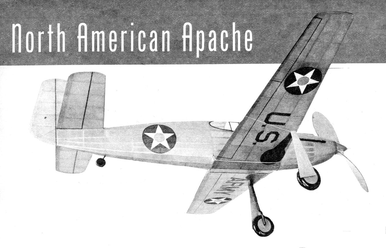
ACCENTING superior flight performance and simplicity of construction, while still retaining the realistic appearance of the real fighter, we offer this month a semiscale model of the North American Apache.
Currently in production at the Inglewood, Calif., factory of North American Aviation, the Apache (XP-51) for the U. S. army air corps and its counterpart, the Mustang, for the Royal Air Force, should prove to he among the outstanding fighting planes of the world. Little information has been released about the ship but it is known to be powered by all Allison engine of 960 horsepower, and to have a performance-improving wing of advanced design. Bristling with eight machine guns and boasting a 412 mile-per-hour speed, it would indeed be all awesome foe.
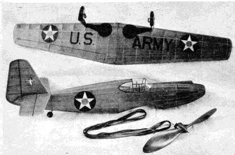
In the model Apache are crystallized the desired characteristics for maximum flight performance and ruggedness of structure. A glance at the photos will verify the model's realism, and while it is very nearly scale, we have in a few instances readjusted the design to obtain greater stability and efficiency. Correctly proportioned tail surfaces and ample dihedral plus efficient setting of the wing and stabilizer produce a model of extreme stability. A powerful motor of considerable length spins the long, effective propeller, making possible flights of good distance and duration.
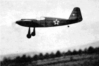
Very little adjustment was required to obtain top-notch flights from our model. With the rubber strands tightly wound, it leaps skyward like an interceptor. This ship, like most low-wings, goes from the power flight to the glide without a tendency to dip or stall. Because of the flat glide and fine stability, we feel that out-of-sight flights are possible tinder favorable conditions.
Construction of the Apache is very simple, yet rugged. Before starting to build, study the plans and instructions thoroughly. Select all materials with care and cement the various joints firmly.
The one-piece wing with landing gear detaches, Your Apache will step along
for
its 90 seconds in saves damage in a crack-up. the air. It is not a floater.

You can't defect variations from scale and your ship will look just like the real one.
CONSTRUCTION
The bulkhead and keel method of construction is used for the fuselage. To obtain the correct shape of the keels, trace the top, bottom and side outlines on 1/16" sheet balsa; each keel may be cut in several sections and then spliced to take advantage of the grain. Full-scale bulkheads are shown, and they, too, are cut from hard 1/16" sheet; two of each are required. Cut only the notches shown, positions of others are marked but they are not cut until later. To assemble the parts, first pin the top and bottom keel pieces to place over the side view, then cement half of the bulkheads to their respective positions--they should be exactly perpendicular to the keels. Attach a side keel, and when this structure is dry remove front the plans and add the remaining bulkheads and keel. Check and recheck for correct alignment.
Stringers are 3/32" square medium strips, or if the builder prefers, he may use 1/16 x 1/8" strips set on end. Attach the stringers nearest the center keel first, cutting the notches with a pointed razor blade as required. Always attach stringers to corresponding positions of each side to prevent pulling the structure out of line.
Members F-1 and F-2 at the wing position are cut from 3/32" sheet. When attached, they should fit exactly to the wing's upper surface. Small blocks of hard 3/32" balsa are attached between the stringers in the rear, as shown, to hold the bamboo pin.
The, sturdy nose provides a place to hold the model while it is being wound. First make the nose block from two pieces of 1/4" sheet cemented cross-grain. Remove the center of the block to receive the nose plug and then roughly cut to shape before cementing to bulkhead 1. The section from 1 to 2 is filled in with soft 3/32" sheet; accurately cut the individual pieces to fit neatly within each space. Once the cement has hardened, the entire nose is cut and sanded to a smooth, accurate shape.
Bamboo splints of about 1/16" diameter are cemented across the fuselage at the position shown so rubber bands call be wrapped about the ends and under the wing to hold it in place.
The wing and landing gear unit are demountable for transporting the model, and since they are not rigidly attached, they will become detached should it fly into some solid object, thus preventing much damage, It will be necessary to make full-size drawings of each wing half from the plan; the chord dimensions can be obtained from the full-size rib patterns. Two of each type rib are required, and they are cut from 1/16" sheet. Carefully sand each rib, then cut the notches from spars with accuracy. Cut the tapered leading edges from 1/8" sheet. Finish the trailing edges before pinning in place over the plan. Cement the ribs, leading edges and tips in place. Spars are hard balsa and all should be attached except the short one to which the landing gear is fitted. Solidly join the two wing halves with 2-5/8" dihedral at each tip. Place the 1/16 x 1/4" landing gear spar and reinforce the joint necessitated by the dihedral. Trim and sand the entire wing to its final shape.
A landing gear of the type required for the Apache always presents a problem for the model maker. However, the landing gear as used on this model is easy to make, accurate in appearance, and will take all the abuse normal flying can give. Bend the two parts of each strut from .050 music wire, using the full-size plan as a guide; they are joined by soldering. Adjust the wires to fit accurately, then bind to the spar with thread. Using a needle and thread saw the other part of the strut right to the rib. Thoroughly coat the thread and adjacent structure with several applications of cement. The rubber tubing covers are not slipped over the struts until the wing is covered.
Wheels are best made from laminated disks of hard balsa, but they may be purchased. Cement bearings to each side so they will revolve smoothly and accurately. They are held in place by washers soldered to the axles, but only after the model has been covered.
Build the rudder over the plan. First make a complete frame using 3/32" sheet for the outlines and 3/32" square strips for the spar and ribs. When this structure is dry, remove it front the plan and cement soft 1/16 x 3/32" strips to each side of each rib. The ribs are then cut streamline and the edges are tapered to blend with the ribs.
The stabilizer is built in one piece over a full-size plan that can be scaled from the magazine page. Ribs and the center spar are merely 1/16 x 5/16" strips; when the structure is dry they are cut to airfoil shape, as shown. Cut and sand the leading and trailing edge, as well as the tips, to their finished shape.
Before the frames are covered, they should be carefully sanded to remove all flaws and roughness. The author likes to sand the fuselage bulkheads to a scalloped shape, thus permitting only the stringers to touch the covering, this aids in making a better job. Once you are satisfied that the frame represents your best work, the covering job may be started.
Either colored tissue or light-grade Silkspan may be used. The latter Is probably easier to apply, but we like the appearance of tissue best. Use banana oil or light dope for adhesive. If tissue is used, numerous small pieces will be required for curved parts of the fuselage, the wing tips. et cetera to avoid wrinkles. Tighten the covering by lightly spraying with water.
If the plans have been closely followed, the wing and stabilizer will have their correct incidence when slipped into place. Firmly cement the stabilizer to the fuselage. Before the rudder is attached, small tissue fillets should be made between the top of bulkhead 12 and the stabilizer. Cement the rudder in place with about 1/16" offset for a right turn. Sand the trailing edge away if the wing fits too tight. so it can move a bit in the event of a crash. A soft balsa block or a tiny built- 111), structure should be attached to the wing's under surface so it will blend neatly with the fuselage lines. As noted before, small rubber hands about tile bamboo splints and under the wing hold it in place, One or two coats of light dope should now be brushed on the whole model. A bit of colored (lope, similar to the covering, added to the clear (lope, will make a more attractive job.
Being a semiscale model. all the realistic detail that can be added without destroying the flying qualities will go a long way in making the ship more worth while. Finish the landing gear by first slipping rubber tubing of the correct diameter over the struts. Wheels are painted and then held to, the axles by washers soldered to the ends. Landing-gear covers are tissue-covered, 1/32" sheet-, they are cemented to the struts rather than the wing so they can spring back and forth with the whole gear. The cockpit enclosure is thin celluloid. Paper patterns for trial fits should be used before cutting the celluloid. Exhaust ports, air scoop, tail wheel and similar details are easily made from scraps of balsa. U. S. army or R. A. F. insignia as well as other details made with tissue will aid greatly in making your model more attractive without harming the flying ability in the least.
Every fine flying model must have an efficient propeller. Select a hard block of the required size and cut the blank as shown. Drill the hole for the prop shaft and then start to carve a right-hand prop. Finish the back face of the blades first, sanding about 1/16" undercamber into each. Thin the blades as much as possible, still letting them retain the required strength. Round the tips like the one on the model shown in the photos. Balance and then finish with fine sandpaper; several coats of light (lope, with light sanding between each, will make a smooth job. .
Details of the spinner are given. On the original we made a complete spinner. The cap was then removed and the center of the back section cut away until the sides fitted accurately against the prop hub. A brass "dog-tooth" freewheeler, as shown, is concealed within the cap, which is hollow. The .050 music-wire prop shaft has a loop in the end into which a winder can he hooked for storing up power.
A removable nose plug makes possible the stretching of the rubber motor for winding. The front disk is 1/32" birch plywood, while the back portion is laminated squares of 1/8" sheet (hard). On our test plane we found that a bit of both down and right thrust was required, so this should be incorporated in the plug. Fix the line of thrust by cementing washers to both the front and back.
The propeller, nose plug and similar unfinished parts should be color-doped to complete the construction.
FLYING
Our model Apache weighs 3.25 ounces complete and is powered by ten strands of 3/16" flat, brown rubber 22" long. Depending on the finished weight of your model, more or fewer strands should be used. Lubricate the motor, wiping off the excess so it will not splash on the sides. Hook the loops of rubber to the prop shaft and then drop the other ends through the fuselage. A removable
bamboo pin in the rear holds the strands.
In all probability a small corrective weight will be needed to bring the plane into exact balance; a tiny piece of lead cemented within the nose was required on the original. Test-glide your Apache, making any weight readjustment necessary to obtain a smooth descent. Once the glide is good, try short power flights, making adjustments exactly the same as with a sport or endurance model. A sliver of wood between the nose plug and nose, tilting the thrust line, will help control the circles, while a bit of downthrust will iron out a stall while under power. As flights improve, increase the number of turns. By stretching the motor and using a mechanical winder, flight performance will be further increased.
The test model performed well from the start. However, it was found that best flights were made when it was adjusted to climb at a steep angle and in a very shallow bank-if the turn in either direction is too steep, most low-wing models will fail to gain altitude. As the torque diminishes, it gradually veers to the right until it is descending in easy right spirals.
Oh, yes, don't forget to put your name and address under the wing.
Scanned from March, 1942
Air Trails
![]()
![]()
![]()
![]()
![]()
![]()
[ Home ] [ Previous Plan Pages ] [ Special
Things ] [ Earl Stahl Plans ]