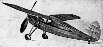
 The most realistic flyer you will ever build |
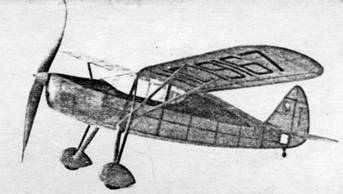 A large high pitch propeller insures long flights |
The Plan Page
[ Home ] [ Previous Plan Pages ]
[ Special Things ] [ Earl Stahl Plans ]
The most realistic flyer you will ever build |
A large high pitch propeller insures long flights |
A FLYING FAIRCHILD 24-K
A Flying Scale
Model That Will Be a Joy To Build and Fly
Beautifully Designed, Strong and of Simple Construction
By EARL STAHL
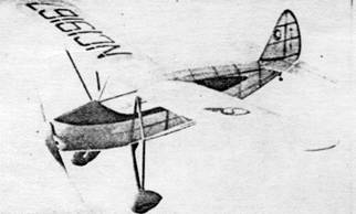
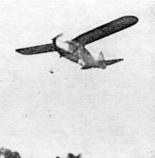 In the air it flies steadily with plenty of power and gives the appearance of a full‑scale airplane |
 Its fine proportions provide unusual stability |
THE new Fairchild "24K," through ingenious engineering, gives all the desired requisites of the private owner plane. Progressive designing over a period of seven years has developed a beautiful, easy to fly airplane with excellent performance. Powered by the new 165 horsepower Ranger in‑line engine, this model features unusual payload and performance characteristics with ample room and comfort for four persons.
Fairchild airplanes have long been noted for their wonderful performance. With a full load of passengers, baggage and fuel, the "24" will cruise for 560 miles at 127 miles per hour. Landing flaps reduce the speed of landings to 47 miles per hour. The rate of climb at sea level is 730 feet per minute and the ceiling is 16,500 feet. Proof of the Fairchild's quality is the fact that the Civil Aeronautics Authority recently contracted for ten more "24's" - this brings to 33 the number they have purchased.
To demonstrate the reliability and stamina of the Ranger engine, one recently was run at full throttle, non‑stop for 50 hours ‑‑‑ equivalent in length of time for a Fairchild "24" to make a non‑stop, refueling flight from San Francisco to Bombay, India, a distance of 6,750 miles. Features of this engine are extreme smoothness, economy of operation and minimum maintenance.
Model builders will find this plane's design excellent for a flying‑scale model. Its aerodynamic set‑up makes long, stable flights possible and the general nature of the design eliminates complicated structures. A well‑built Fairchild model, if properly adjusted, will be capable of making flights of more than a minute, and whether on display or in flight its appearance is striking, indeed. Of interest is the fact that the model was developed directly from plans and data supplied by the Fairchild factory.
Construction is not difficult. Study the plan thoroughly and read the instructions before beginning actual work. Build directly over tracings of the plans; don't cut or spoil the pages of the magazine. Cement all joints firmly and make the structure accurate at all times.
Fuselage
The fuselage is constructed in the conventional manner. Two 3/32" sq. side frames are built and then joined together, as indicated by the top view, to form the basic fuselage structure. As shown, a 3/32" rib is fitted into correct position as part of each side frame in order that the wing can be accurately attached in the final assembly. Halves of each of the formers are shown on the plan; they are all cut from 1/16" medium grade balsa. Cement them into place and attach the 1/16" sq. stringers. In the event notches aren't cut in the formers, the stringers are simply glued atop them. Side stringers are glued directly to the sides of the underframe.
The shaded area of the nose is covered with soft 1/32" sheet balsa. Use the widest stock available and glue the covering to the entire adjacent frame. If the curvature of the nose causes the sheeting to stand away from the formers, cut slivers from it to make the covering fit tightly. Plenty of pins and rubber bands will be needed to hold the covering in place until dry. The nose block is cut from a piece of medium grade balsa; and once it is glued into place its shape is sandpapered to make it blend with the sheet covered nose.
Landing gear legs are attached to the fuselage before it is covered. A continuous piece of .040 music wire is bent to fit to both bottom longerons of the fuselage, as shown by dotted lines, and then extend down the struts to form axles for the wheels. Neatly bind the wire to the longerons with thread. The landing struts are cut to shape from extremely hard 1/8" sheet balsa or even white pine. All struts are streamline in cross‑section; a groove on the inside of the legs concealing the wire, and thread and glue will hold the struts to the wire. The tops of the struts are not glued to the fuselage and a small gap is left between them to permit the gear to spring back and prevent damage to the fuselage in the event of a hard landing. The remainder of the landing gear is completed later.
Tail Surfaces
Scale tail surfaces are shown on the plan and the test models flew very well without any changes but for those who aren't too interested in exact scale, we recommend the use of a slightly larger rudder at least. The stabilizer is built in one piece for strength. The rudder and stabilizer are constructed similarly. A complete frame is built using1/16" sq. balsa for ribs and spars and 1/16" thick outlines. When dry 1/16" x 3/64" strips are cemented to both sides and cut streamline to form ribs. Tail surfaces constructed in this manner will not warp easily.
Wing
The wing is made in two parts, the right and left halves. It will be necessary to make a left wing plan since only the right half is shown. Fourteen ribs cut from soft 1/16" sheet are needed: 10 are regular ribs, 2 are tip ribs and 2 ribs that join the fuselage are cut to the shape shown by the dotted lines. This is not the scale airfoil it was substituted to provide better flights. Stack all like ribs together and sandpaper them to insure that they are identical. The inner ribs are tilted slightly so the dihedral angle will be correct when assembled. Very hard 1/16" sq. spars are used. Cut and sandpaper the leading and trailing edges as well as the tips to their proper shapes when the assembly is dry.
Propeller
Carve a propeller from very hard balsa. The size of the block is 1" x 1‑5/8" x 9‑1/4". Lay out the blank as shown. Always cut the back face of the blades first. The hardness of the wood will determine the thickness of the blades, the shape of which can he seen in the photos. The spinner is made in two pieces which are glued to the sides of the prop hub. About four coats of clear dope, with light sanding between each application, will produce a smooth finish. Equip the model with some kind of a free‑wheel device so the glide will be improved.
The nose plug is made to fit the hole in the nose block. Its back is a piece of very hard balsa while the front disk is made from a piece of 1/32" plywood. It is advisable to drill the hole through the plug so about two degrees of both right‑ and down‑thrust result. Glue washers to either end of the hole through the plug.
The propeller shaft is bent from a piece of .040 music wire. Place several washers between the prop and nose plug and bend a loop for a winder on the front of the shaft. A catch on the shaft will keep the wire from straightening when there is tension on the motor.
Covering
A neat attractive covering is a "must" for any fine flying‑scale model. Colored tissue is used and since this is a commercial plane, most any color combination will be correct. Every bit of the structure is lightly but thoroughly sandpapered to properly prepare for a neat job. Cement cellophane side windows into place before starting to cover the fuselage. Bear in mind that only the longerons and stringers should touch the covering; if any formers might touch the paper, sand them enough to prevent it. The use of numerous small pieces on curved parts will help prevent wrinkles; on such parts as the top of the fuselage, five or six pieces will be needed to complete the covering. Use only enough banana oil adhesive to stick the extremities of the area being covered and lap the separate pieces carefully and neatly. The cowling and other similar parts are covered with tissue, too. Use several separate pieces of tissue on wing tips, etc. Adhesive should be applied to every rib and spar of the wing's undersurface to preserve the airfoils shape, otherwise just stick the covering at extreme edges. Once covered all parts are lightly sprayed with water to tighten the tissue. The tail surfaces and wings should be pinned to a flat surface in order that they don't warp. Any tissue decorations, such as license numbers and control surface outlines, should be cut from contrasting tissue and placed into position. The best way to do this is to brush light dope over the tissue trim, once it is in place, rather than trying to place it accurately after the adhesive has been applied. It is not difficult to improve the model's appearance with these scale effects, and it is really worth the time and effort expended.
Assembly
The parts are now assembled to complete the construction. Cement the windshield into place first; the pattern given may not fit your plane exactly so alter it if necessary before cutting one from celluloid. The stabilizer is slipped into place and then cemented fast. Offset the rudder enough to make the model glide in right circles -- it should be exactly perpendicular to the stabilizer. Little difficulty will be experienced in placing the wing since the fuselage has built‑in ribs with the correct incidence. The dihedral at each tip is 1-1/2"and bottles, cement cans, etc., can be used as supports until the cement is hard. Wing struts, shown in dotted lines with the wing plan, are made from 1/8" x 5/16" balsa strips. Sand them streamline and color dope them before fitting them in place; the length may need slight altering to fit your plane exactly. Cut the tissue from the wood at the junction of the struts and wing, etc. Wheels are 1-3/8" in diameter and they can be made from laminated balsa discs, or they may be purchased. Wheel pants improve the model's appearance. but they can be eliminated, if desired, since only deluxe models of the Fairchild are equipped with them. The shock strut of the landing gear is cemented firmly to the pants as shown, but the top is held in place by a small piece of soft wire which will permit the whole landing gear spring back and forth without damaging the model. Color dope the propeller and wheel pants, if used, and add any minor details to complete the model.
Flying
Flight tests should be conducted over tall grass or weeds to prevent damage to the model. Depending on the model's finished weight. 10‑12 strands of 1/8" brown rubber will be needed. The rubber should be lubricated, but remove any excess lube before placing the rubber in the fuselage to avoid splashing the sides. A 1/16" diameter bamboo pin holds the rubber motor in the rear. Test glide to determine if the balance is correct: addition of a bit of weight to the nose or tail will correct a stall or dive as the case may be. Once the glide is good, all power flight adjustments should be made at the nose plug. Tilt the line of thrust down to correct tendency to, 'mush," and to the right or left to control the circle. The model pictured flies and glides in large right circles. For maximum flights attach a mechanical winder to the hook on the prop shaft ‑ stretching the rubber before winding. The maximum number of turns is about 850. Get out in the wide open spaces to fly your "24," since it will probably fly in a manner to rival your endurance models.
Scanned
from February 1940
Model Airplane News
![]()
![]()
![]()
![]()
[ Home ] [ Previous Plan Pages ] [ Special
Things ] [ Earl Stahl Plans ]