The Plan Page
[ Home ] [ Previous Plan Pages ]
[ Special Things ] [ Earl Stahl Plans ]
Modeling the Cessna 195
by EARL STAHL
AMONG the widely used executive-type planes is the Cessna 195. Its purchase price of nearly fifteen thousand dollars keeps it from most private plane buyers, consequently many of the 195's are owned by businesses, which require the swift, comfortable transportation it provides.
From most every point of view the 195 is a remarkable craft. With a cruising speed of over 165 mph and a luxuriously outfitted cabin, it matches many air liners for speed and comfort. Pilots like the 195, for it flies with the ease and safety of most light training planes. Equally important, is its ability to operate from the smallest airports, thus making it possible to take the ship just about anywhere a plane can safely land and take off.
The Air Force has recognized this ability to fly from restricted areas and has purchased 195's for rugged Alaskan duty. For service of this kind, wheels are interchangeable with skiis and floats.
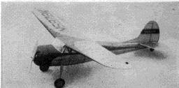
Capturing the attractive appearance and good flying qualities of the prototype, this model will more than compensate for the time and effort required for its construction. An O.K. C02 expansion-type reciprocating engine was installed in the original model, but the design may easily be altered to utilize rubber strands or a small gas engine for power. In any case, work carefully, using the plans and text as a guide, and your model 195 will surely take to the air as readily as a duck takes to water.
Conventional model construction practices are used throughout. Balsa wood is required for most parts and the various members are fastened together with fast drying, colorless cement.
Many assemblies can best be built right over full size drawings so the first task is to double the magazine-size plans. To do this, step off each dimension twice using dividers. Where curved parts are shown, one-half inch grid is imposed on the magazine page to speed the job and increase the accuracy.
The fuselage is a simple yet strong structure. Four keels (two side, a top and bottom) are cut to shape from 1/16" balsa sheet and then the 1/16" thick formers and 1/16" sq. stringers are added. All parts are medium grade balsa except the stringers, which are hard balsa. Assembly is accomplished most easily if the top and bottom keels are pinned to position over the enlarged drawing; half formers and a side keel are then attached. Once this structure is dry, it is lifted from the jig and the remaining parts attached. Forward of former No. 1, a 1/4" thick bulkhead identical in diameter to former No. 1 and radiused as shown is attached. This member retains both the motor mount and cowl.
Before the cowl is cemented in place, it would be best to install the O.K. C02 engine. Bolt the engine to the mount. Then cut a notch in the solid bulkhead to pass the pressure line. The cartridge holder is sewn by needle and thread to former No. 3, off set from the center line, as shown, to by-pass the bottom keel.
The landing gear is a single piece of .045" music wire sewn to former No. 2. A 1/32" balsa fairing held in place by silk covering over both the wire and balsa adds realism. Wheels are balsa, and they may be purchased or turned from laminated balsa discs. In either case, they should have bearings cemented to the sides so they will revolve freely and accurately.
Three parts are required for the wing assembly, the right and left panels and the center section. Cut the parts out as indicated, ribs and spars from 1/6" sheet balsa, leading edges and tips from 1/8" sheet, and the trailing edges from 1/8" x 3/8" strips. Assemble the parts over full size layouts and then join all three sections with 1-1/2 dihedral at each tip. Finally trim the leading and trailing edges to the cross sectional shape indicated.
The horizontal and vertical tails are light and strong, if built as suggested. Cut outline pieces from hard 1/16" sheet balsa. Add 1/16" sq. spars and ribs. Lift these flat structures from the jig, and add 1/16" sq. strips to each side of each rib; these are then cut to conform to the streamline rib shape shown by the sketch. To complete the tails, trim and sand the outline pieces to blend with the rib cross section.
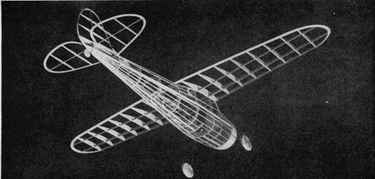
Before frames are covered, they must be sanded to permit a neat job. Don't be deceived by the pictures of the structure of the original model; the parts actually should not be assembled until they are covered. First cement cellophane to the side windows. Now the fuselage may be covered. Colored tissue was used on the original and it is both attractive and serviceable. Work carefully, using as many small sections of tissue as is necessary to avoid wrinkles. Attach the individual sections of tissue with banana oil or light dope. When the covering job is done, lightly spray the parts with water to shrink the tissue but do not apply any dope to the covering until the entire model is completely assembled.
To assemble the 195, follow this sequence: first cement the wing to the fuselage making certain that it is correctly aligned. Slip the stabilizer into the notch between formers No. 8 and No. 9. Cement the rudder atop the fuselage, off-setting the leading edge several degrees to the left so the model will glide in right turns. Check the tail surfaces for correct alignment. The whole model may now be given two coats of thin clear dope.
Trimming and minor details complete the construction. The front windshield is light weight celluloid and it is cemented in place. The side window outlines on the test model were realistically represented by cutting them from dark tissue and working the dark tissue into a decorative color scheme. License numbers are likewise cut from dark tissue paper, dummy tail wheel should be added and the main wheels and other external wood parts painted, of course.
To prepare the model for flight, a C02 cartridge is slipped into the holder, but before any flights are attempted the position of the center of gravity should be adjusted. When supported by the finger tips under the front spar, the fuselage top should be level. In the event it is not, add weight in the form of small pieces of lead to the extreme nose or tail to attain this attitude. Glides should be smooth descents from shoulder height and any erratic performance should be corrected through further weight redistribution. First power flights should be with reduced power achieved by slightly unscrewing the engine cylinder (1/16 of a turn at a time until power is right), or by simply not launching the model until some of the energy has been exhausted from the cartridge. Minor adjustments may be made by slightly warping the flying surfaces. In the event glides are satisfactory but power flights show a tendency towards stall, tilt the thrust line down slightly by inserting small washers behind the top lugs of the engine mount.
Treat your Cessna model right in building and flying and it will treat you to countless pleasurable experiences.
Scanned from April, 1950
Model Airplane News
![]()
![]()
[ Home ] [ Previous Plan Pages ] [ Special
Things ] [ Earl Stahl Plans ]