|
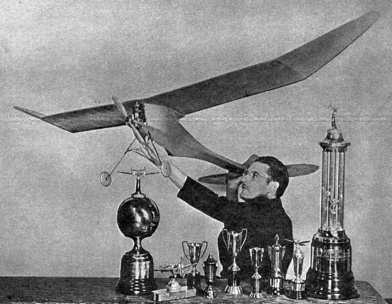
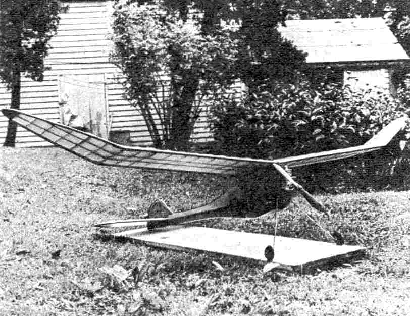
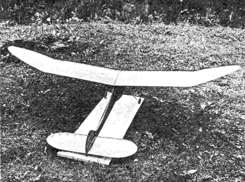
FOOTE'S "WESTERNER" THIS 7' CLASS C CONTEST WINNER IS THE MOST OUTSTANDING DESIGN THAT HAS BEEN DEVELOPED SINCE THE PYLON ERA. BUILD ONE NOW, TO ASSURE YOUR SHARE OF TROPHIES IN POSTWAR CONTESTS.
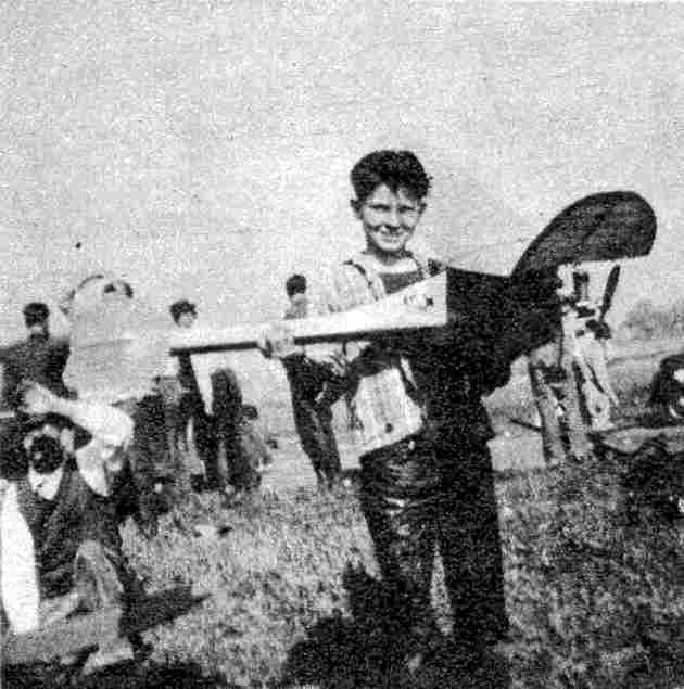
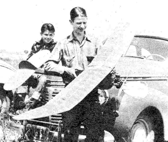
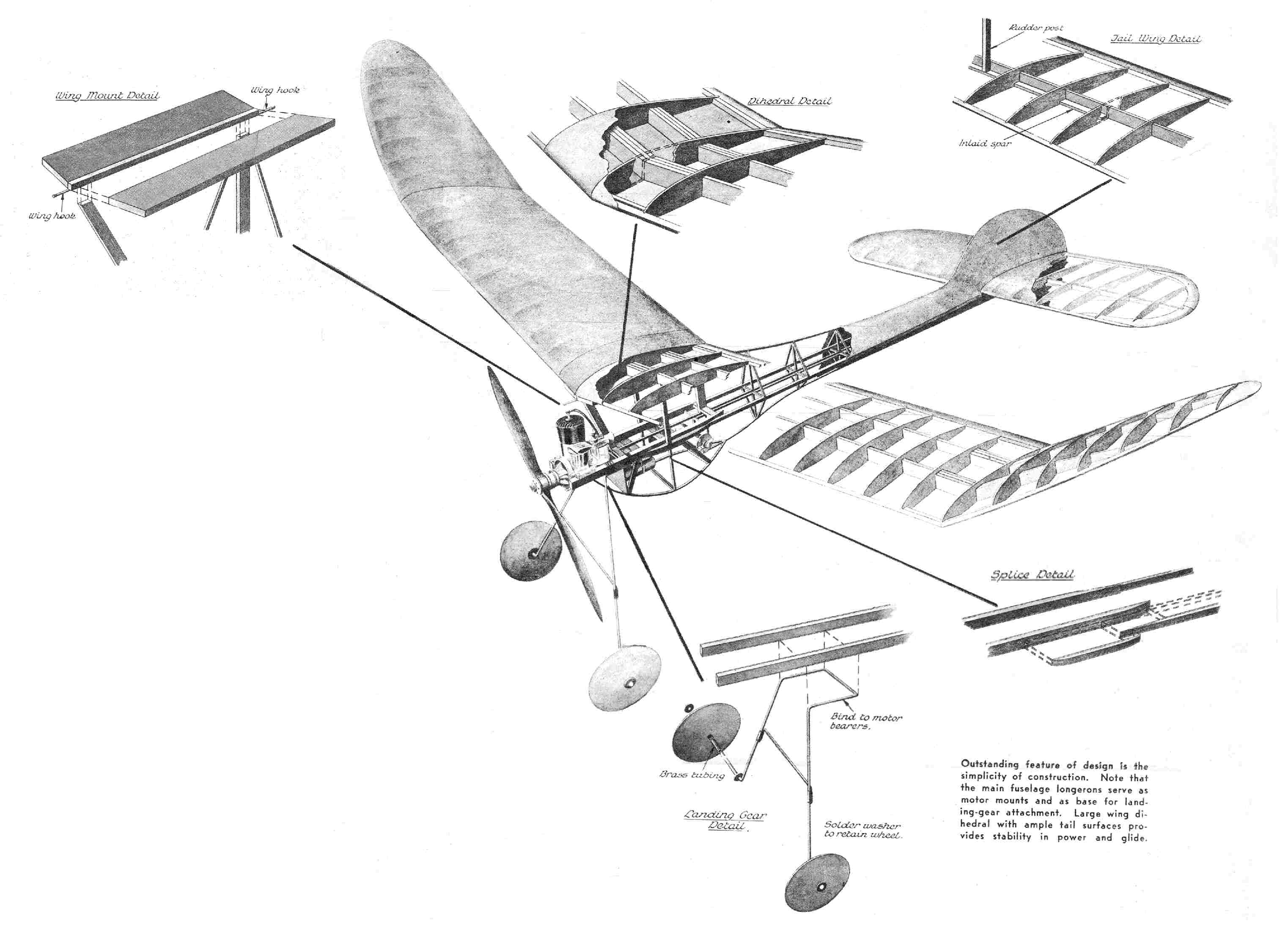
HIGH-PERFORMANCE contest planes are distinctly not designed. Instead, they develop over a long, grueling period. In that time the bugs are ironed out, the essentials are improved and the nonessential items are trimmed away. Out in California, where the Westerner was evolved, competition was, and still is, really tough. Modelers were able to fly and test ships from sunup to sundown. They constantly sought out the hottest motors, and every contest was a knock-down-and-drag-out affair from start to finish. Prior to 1941 the author was engaged in developing the ship that ultimately proved to be the Westerner. When the contest season started that year, we fondly hoped that the "bugs" had been eliminated. The ship that evolved was heavy, weighing over twelve ounces per square foot, but it would take the hottest motor available without spin or other disastrous result. Besides, it was rugged almost to a fault, and would glide with the best of them once it got up there. And get up there it did, with almost any motor. After much testing the Westerner launched the 1941 campaign and from start to finish of that season it made modeling history. During the period, the author, flying the Westerner, won an O. K. Special, an Ohlsson 60, Ohlsson 23, Thermite 60. Thermite 43, Thermite 36, Dynamite, Micro 19, two awards of $50 cash, other cash awards of $12.50, and nine different trophies. It won the San Francisco Bay area trophy three times and the East Bay Aeroneers trophy eleven times, retiring both of them. The prizes mentioned were all for first places and in the contests entered the winner of first had a choice between trophy and motor. The ship took twenty first places. In addition to other awards, the Westerner took home enough model supplies to stock a hobby establishment. On the day the Westerner set the AMA record for Class C R. O. G. Open, the weather was ideal for flying, with no wind and plenty of thermals. The meet was held at Sacramento, Calif.. in the fall of 1941. The currents were not enough to put a ship out of sight. but as soon as one quit there seemed to he another handy. After three flights the Westerner was found to have averaged 24:37.8. Second-place winner averaged 14:40.6 -So you can see the difference in performance. Manuel Andrade, the author's flying pardner at the contest, watched the ship for the first flight, chasing it out several miles. At that point the ship hooked a ground thermal and began to ride up almost out of sight, then down to within 100 feet of the ground, and back up, et cetera. Manuel fell asleep alongside the road and was awakened by a motorist who thought he must have been hit by a car. After more than an hour the ship came in to a perfect landing. The writer chased the ship on the second flight and had much the same experience. We had lunch, watching the ship in the meantime, and recovered it after it had flown - to our knowledge - over two hours. More incidents about the Westerner could be written and all would be interesting to modelers. The ship was put out in kit form for a short period, but wartime restrictions caused it to be withdrawn from the market. Buddy Romak, whose entire family fly Westerners, holds the Class B R. O. W. record - with a scaled-down version-and held the Class A R. O. W. record for some time until it was recently broken. The original ship holds the Class C R. O. W. AMA Open record with an average of 2:48.4, the highest R. O. W. record listed. Many fliers who had never won a contest in their lives immediately became top-notch fliers upon completion of their first Westerner, and few of the modelers have switched to other types after flying one for a time. The ship has been scaled clown to fit smaller motors, with equal success. It is hardly possible to overpraise such a ship. Build one and you'll see why the Westerner is tops among Class C contest ships. CONSTRUCTION Your first impression may be that the Westerner is ungainly. However, each part has been carefully designed to give the utmost in performance combined with the greatest strength. The entire fuselage is sheet-covered with 1/16" sheet. The motor mounts are of rock-hard maple or similar wood. All wood used is hard and construction is rugged throughout. The wings are of especial interest because of the sweepback. Inasmuch as tips on model wings stall first, sweepback in them eliminates this fault to some extent and improves the stability. The tail surfaces are cemented to the body. This makes transportation a problem, but eliminates possibility of changing adjustment and tail members falling from the plane when a hot climb is under way. Build the plane as directed, It may weigh a bit more than you planned, but it will take the hottest Class C motor on the field and turn in a record performance. There are several other innovations in the Westerner. The fuselage is entirely covered with 1/16" sheet balsa and this covering plays an important part in furnishing additional strength. The fuselage framework is of 1/8" square (hard) in all but a few places. It will be necessary to make up your own set of plans from the drawings. All dimensions are given, and although the full-size plans will require some effort, you can easily do the job in an evening, using nothing but a convenient drawing board or table top, a ruler and a pencil. Concentrate on plans for the fuselage first, for that portion of the ship should logically he the initial step. The top view of the fuselage (Plan 3) should be drawn out on a large strip of paper. Begin your building by selecting two pieces of 3' hard balsa 1/4" square for the longerons. The motor mounts are of rock maple, although any hardwood will do, such as gumwood, oak, ash, or even spruce. In the original ship these mounts were 3/8" x 1/2" hard maple. The width of your ship will depend upon the width of the motor you plan to use. For a Brown, or an O. K., the motor amounts should be 1-5/8" apart. Splice the mounts to the 1/4"- square longerons and build the section flat on the board, using 1/8"- square crosspieces. Note that these crosspieces are even with the bottom, or flush with the building board. While the section is drying, cut the center stringer of the wing mount from a piece of 1/4"- square hard balsa and cement front and rear wing hooks to it, wrapping each securely with linen thread which is, of course, smeared with cement to make the mounting firmer. The top side view, shown as Plan 1, is next assembled. Cut the uprights of the wing pylon from pieces of 1/4" x 1/2" sheet. Lay out the long stringer which extends from the bottom of the pylon to the rear of the fuselage. Assemble the entire plan, noting in particular that the long stringer is centered on the pylon uprights. As a third step in building, construct the bottom half of the side view. This is built entirely of 1/8" square. You now have three sections of the fuselage complete, and are ready to begin assembly. With the long section, which includes the motor mounts, still on the table, cement the top side view on securely. All cross-member points should meet exactly. You'd better use a square to be sure that the side view is not only exactly perpendicular, but also centered on the main longeron section. Complete this assembly by cementing the pieces of 1/4" square alongside the splice of the longerons and motor mount. Cut out the wing-platform pieces and cement them to the center stringer of the same in proper angle. which you may find by looking either at cross-section plan or the center dihedral former. Insert the upright pieces of 1/4" square which extend from the side of the motor mounts (over the splice piece) to the side of the wing mount. When the above assembly is dry, insert the diagonals which go from the main longeron to the top of the rear fuselage. These are of 1/8" square; note that they are set in 1/16" from the side of the longeron and at the top come flush with the 1/8"- square piece extending from the rear of the pylon to the tail. This accommodates the 1/16" sheeting and allows it to come flush with the longeron. The next step, and still without removing the top half from board, is to sheet the entire assembly from the front pylon former to the tail. It is advisable to form the rudder at this point, for it attaches directly to the top longeron. The rudder outline is formed from 1/16" soft-iron wire. Lay out the full-size rudder first and then bend the wire carefully to the outline. When completed, attach it securely to the top longeron with linen thread and cement. Wrap it, merely for the time, at the rear, and finish the sheeting process. Two pieces of three-inch should do this easily, but if using two-inch sheet, make top and bottom attachments first and center strip last. It is easier to fit that way. The wire - outline rudder looks rather odd, but it holds position better than any other method, and adjustments, once bent in, will remain. When the top half of the fuselage is dry, you may insert crosspieces and finish the rudder, except for the bottom portion. If your model is built over a board, it is best to let the extreme tip of the longeron protrude beyond the board so that the wire forming the skid will not be bent until later. When the entire top half is done; remove it from the board and lay it on the wing mount, bottom side up. Cement the bottom half of the fuselage in position. Note that from the upper end of the bottom upright to the motor mounts two pieces of 1/8" square separate and curve around in much the same manner as a wingmount curve. At the midpoint of the pylon on the bottom half, pieces of 1/8" square make up a box cross section, the widest part in the curve. Directly beneath the point where the pylon meets the main longeron is a 1/16" sheet-balsa firewall, which may also be made of birch plywood. The landing gear, of course, will have to be formed and lashed into place before the bottom half of the fuselage is sheeted. Measurements are given on the plan. A good-grade 1/8" landing-gear wire should he used. It is lashed to the motor mounts in two places. Despite its length, it is not ungainly, inasmuch as it saves countless props and greatly aids take-off. Diagonal pieces of 1/8" square are used in the construction of the bottom half of the fuselage, in the same manner as used in the upper portion. When the entire assembly is finished it is sheeted with 1/16" sheet, including the bottom section under the pylon. Cut-outs are made later for the battery, although coil and timer should be inserted prior to covering the front portion. The final step in the fuselage is completing and lashing the rudder to the ship. SURFACES Templates are given for construction of the elevator. Construction is simple; note in particular the strong bracing employed in the elevator main spar, which enables the rudder to be made practically a part of it. The wings cannot be called conventional, either in outline or construction. Note that pieces of wood are used as jigs to insure proper incidences. It is best to make a full-size drawing of the wing and follow it closely, preferably building over it. The original ship was covered with medium-weight Silkspan, although many have used silk or bamboo paper. It is best to give the fuselage several coats of clear dope, sanding between each of them, and then at least two coats of color dope. The wiring diagram is conventional. The booster plug is installed on the opposite side of the ship from the timer. When complete, the ship balances at a point almost 2/3 back from the front of the wing mount. The point is marked on the drawings. Complete with motor, batteries and wheels, the ship should weigh about three pounds. Wing area is 769.7 square inches or 5.35 square feet. So far as possible all incidences are built into the ship and appear on the plan. The ship does not turn in the climb, but under full power makes an almost steady drive for the clouds. Test the Westerner carefully on its initial flights. If it appears to stall severely, place a bit of 1/16" sheet balsa under the trailing edge of the wing, increasing the thickness of this piece until the glide is level. If the ship dives, put the pieces of balsa under the leading edge of the wing. The Westerner is rugged, inherently stable, and decidedly a contest model. It will win for you, and once you have built the ship you will be firmly convinced that the Westerner has "got what it takes." Scanned From August, 1943 |
