How you can build a speedy modern
pursuit type U-Control model that is easy to fly
by JERRY BROFMAN


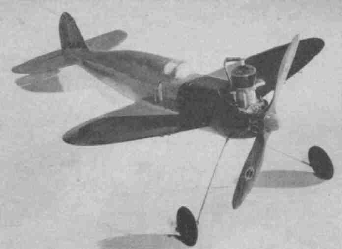
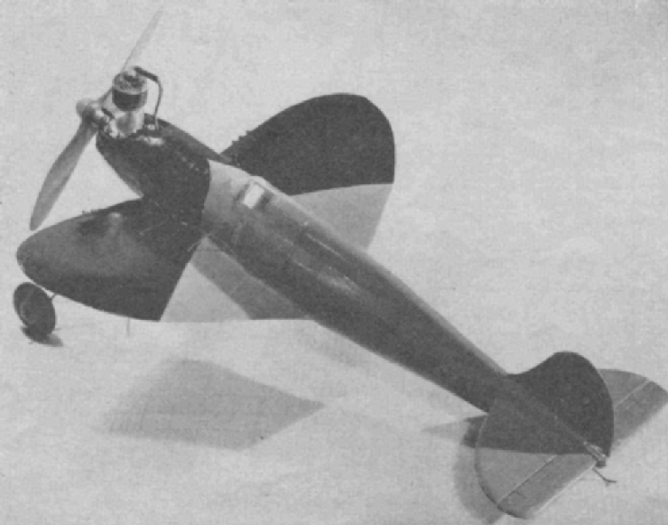
The sleek streamlined speedster ready for action
DURING past contest seasons -- when
free-flight gas models were in vogue and gas and cars were plentiful --
modelers tried for long, high flights. Few modelers ventured to the field
with realistic looking ships, and the contest airplane was getting to look
like anything but an airplane. Some said this could not have been helped;
and some said it could have been helped. "Dyed in the wool" contest
builders criticized fellows who brought to the field anything that
resembled a real airplane. They said that their crazy looking contest jobs
would win -- and usually through luck or logic their crazy looking jobs
did win!
Nowadays, with gas, cars, flying fields,
motors, balsa (one could go on forever) being scarce, U-Control models are
being seen much more frequently; in fact, there are very few free-flight
fans left who would risk losing a motor that cannot be replaced, on a
thermal flight without a car to chase. These now popular U-Control ships
can be made either to exact scale or semi-scale; at least, they can be
made to look like a real airplane without the loss of flight efficiency.
They also can be given beautiful paint jobs with many details, such as
machine guns, bombs, etc., and can be built strong and streamlined to last
very long. There is fun and much knowledge of "hot" flying military jobs
gained in controlling these little "speedsters."
Now, to tell you something about our
Thunderbolt. She was designed to resemble the average fast pursuit ship of
today. Its internal structure reminds one of the Republic P-47
Thunderbolt; it is very compact with a place for everything and everything
in its place! There is little room to spare for anything after ignition
and controls are in. It also is like the P-47 in that it is slightly heavy
for its area, slightly small for its power and "built like a brick" to
last.
If you build the Thunderbolt you will
not only have a realistic, good looking U-Control model, but one with
amazing flying ability, whether you are interested in control or speed.
Start by scaling up the plans to full
size. Next cut fuselage formers to shape. These are made of 1/8" balsa,
1/16" pine or both. The original ship was made entirely of 1/16" pine
formers, except where noted on the plans. Cut the two side longerons of
3/16" square pine to their exact lengths, as shown on the fuselage top
view. Do the same for the bottom 3/16" square pine longeron. Then steam
and pin it :to the side view to get the correct bend. Assemble the
fuselage by marking off the places on the three longerons where the
formers fit. Insert the two side longerons first and cement them to the
formers. Use rubber bands to hold the rear bend in place.
The wing is made .next. Cut two wing
halves of 3/8" x 2" sheet balsa. If balsa is not available, pine can be
used if the center is cut out and 1/16" pine ribs inserted at 1-1/2"
intervals. Cut the wing to rough airfoil shape as shown on the plans;
finish off by block-sanding as you would a handlaunched glider wing. Join
the wing halves with 1" dihedral in each tip-give this joint at least
three coats of glue.
When the wing is dry it is cemented to
the fuselage. It fits on the bottom of formers B, C, D and E and flat
against former F. Cement it very firmly to these formers, as it will take
much stress at high speeds and "hot" landings. Cement the bottom of
formers B, C, D and E to the bottom of the wing. When dry cement the
steamed and bent bottom longeron to the bottom off the fuselage formers.
Steam and bend the rear top longerons as you did the bottom one. When dry
cement it to the rear top formers from former E to former J.
Front top formers of the removable hood
are now cut, and the removable hood is assembled. This hood, as shown on
the plans, holds all the ignition, including battery box. This is very
accessible. The ignition can be put in now. The battery box is made of
sheet balsa and fits between hood formers E and F as shown on Plate 3. The
coil is glued between the two balsa blocks, which in turn, are glued
between the formers as shown on Plate 3. The batteries come out through
the bottom. A switch is used in place of a timer. Cover the hood with
1/16" sheet balsa just as the rest of the body is covered. Cut two motor
mounts of 3/8" and 1/2" gum or basswood and insert in the first two
formers, which are made of plywood. Cement the mounts in thoroughly, using
extra coats of cement to insure strength.
Bend the landing gear of 3/32" steel
wire to shape, as shown on Plate 2, and bind it to the firewall with soft
iron wire. Coat the firewall with at least three coats of cement to keep
the gear on firmly and prevent gas seepage into the fuselage. Carve the
nose block (of soft balsa) to shape and cement to the mounts and firewall
as shown on plans. Sand and shape to body contour.
Cut the control pieces from 1/8" plywood
as shown on Plate 2. Assemble the two control pieces with the 3/32" steel
bolt as shown. Bend the control wire of 1/16" steel wire -- 15-1/2" is the
length -- but it might vary on different ships. Cement the finished
control unit into the bottom fuselage half right over the wing as shown on
the fuselage plans.
Cut the elevators, rudder and stabilizer
all of 1/8" sheet balsa. The 1/4" x 1/8" pine strip is cemented to the
elevators as shown. - Linen hinges are used to hold elevators to the
stabilizer. Cut and bolt the aluminum control fitting to the 1/8" x 1/4"
pine strip. Cement the stabilizer-elevator unit to the fuselage longerons
as shown. Attach the control wire to the aluminum control fitting on the
elevators as shown on the plans; that is, with washer and solder on each
side, allowing the fitting to swing loose around the wire. See that the
elevators go up and down about 1/4" in each direction when you pull the
control lines. The stabilizer-elevator unit is cemented firmly to the
fuselage longerons as shown. The top rear balsa block is cemented to the
top of the stabilizer; the bottom block is cemented to bottom of the
longerons. The rudder is cemented to the top balsa block. Remember to
offset the rudder about 1/4" to the right -- against the turn of the
circle being flown around.
The 1/8" x 1/4" pine strips should now
be inserted from, former E to former H. When dry sand the entire fuselage.
Cover the fuselage with 1/16" sheet balsa. Use a 3" sheet to cover the
bottom from former F. Use 1-1/2" sheets to cover the space on top of the
wing from former A to F. Use 3" sheets to cover each quadrant of the rear
elliptical crossection from former F to former J on bottom, and from
former E to former J on top. Steam the sheet balsa if you find bending it
to the fuselage curve is too hard. Be sure to cement the sheets to each
and every former -- use pins liberally. When dry, remove pins and sand
smooth. Start with No. 1 sandpaper, and finish with 6/0 sandpaper. Give
three coats of thin cement over sheeting and fill in any cracks and seams
with wood filler. Sand between each coat. Apply three coats of colored
dope. The original was black in front, and orange in the rear, as shown in
the pictures.
Bolt down motor with about 1/16" right
thrust, against the circle flown around. The control lines are of 45 lb.
for the Forster "29" or similar class B motor; 60 lb. test. should be used
for larger Class C motors. The lines go through 3/16" aluminum or brass
tubing, set in horizontally in the wing, shown in the top and front views
of fuselage in Plate 1.
Attach the hood to the fuselage, by
inserting the 1/16" dowels in their respective holes in the fuselage.
Connect the high tension lead to the plug, the point wire to the points
and the ground wire to any one of the motor bolts.
Test the motor before going to the
field. Be sure it runs smoothly on your inside batteries. See that the
control lines work smoothly. For test flights, it is best to fly in a dead
calm. Have your helper get the motor running at about half throttle for
the first flight. Let the ship roll and gain speed. Give the up-line a
little pull and she will hop into the air. Notice that at neutral control
she will fly by herself. She will not go into the circle at you, because
of the offset rudder and thrust line. Try the controls for up and down --
do not over-control -- just a little pull is necessary because of the
large "flippers" (elevators). On the next flight, run the motor more if
you are sure you understand the controls.
With a little practice, exciting speed
and tricks may be performed by pilots of this "Leashed Demon."