|
MODELING YOUR FUTURE IN AVIATION Official Air Youth course in By CHARLES H. GRANT LESSON 9 Planning and building an elementary contest glider
THE first model described in this series of articles was the "bird glider," designed with the proportions and contours of a real bird. For stability and control the bird moves its wings and tail, thereby retaining balance. However the wings and tail surfaces of a model glider necessarily must be rigid. This deprives it of the required stability unless tail surfaces are much larger than a bird's or are placed farther to the rear of the wing; because longitudinal, or fore and aft stability is proportional to the stabilizer (horizontal tail surface) area times its distance from the wing center (stabilizer moment arm). The distance from wing to stabilizer in the bird glider was kept constant to retain bird proportions, so tail surfaces were increased in area to provide required stability. However, only sufficient area to give it minimum stability was possible without making the tail excessively large. Plans and description of other gliders patterned from full scale planes followed the bird glider. These, too, had minimum longitudinal stability, when made to the exact scale of the large plane. Though the moment arm was much longer the tail surfaces were small for complete stability, because they were fixed and not movable for purposes of balance like man-carrying planes. To produce the stabilizing or control effect of movable horizontal tail surfaces, fixed stabilizers must be at least two-thirds larger. Though in several glider designs the tail planes were enlarged slightly from exact scale, to increase longitudinal stability, but were smaller than required for complete stability. So in the designs of both bird glider and gliders built to scale of large planes, stability was sacrificed to retain scale proportions. This usually occurs whenever flying models are built to exact scale of large planes. When stability and flight efficiency alone are sought, design proportions must be dictated solely by aerodynamics and not by some particular structural pattern; some full scale airplane or bird. What are the basic proportions for an efficient and stable glider? Let us design one and see. The starting point or basic measurement is always the wing span because all other airplane measurements must be proportionate to it. (Span is the distance from one wing tip to the other.) To keep construction simple and cost low, the glider should be of moderate size: a wing span, S, of 16 inches is satisfactory. Less than this makes flight erratic and adjustment difficult. The next feature to consider is length of wing chord, the distance from the leading or front edge of the wing to the trailing or rear edge. An average value is about 1/7 the wing span, so wing chord, C, is 2-1/4 inches. This relation between span and chord is called "aspect ratio" and is represented by: Span/Average Chord = S/C = 16/2.25 = 7.1 Location of the tail planes is determined next : the moment arm, M, must be long enough to provide stability without excessively large tail surfaces. A length equal to 1/2 the wing span is standard, so tail moment arm, M = 16/2 = 8", = distance from wing center to center of the stabilizer. Now the stabilizer size and proportions for complete longitudinal stability must be established. Stabilizer span SS = (0.4) X wing span S = 6.4". Stab. chord Cs = (0.85) X wing chord C or Cs = 1.9". This gives a stabilizer area AS of 12.16 sq. in. When the tips are rounded as shown on the plans, area will be about 2 sq. in. less or 10.16 sq. in. As a basic rule, stabilizer area of a glider should be about 30% of the wing area. The wing area is 36 sq. in. less 2 sq. in. for rounded wing tips, or 34 sq. in.; so the stabilizer area of this glider is just 30% of the wing area. Fin proportions are governed by the wing as the wing alone causes directional instability which the fin controls. However stabilizer measurements are also proportional to the wing, so fin measurements may be determined relative to stabilizer span and chord. Fin height is (0.43) of stabilizer span SS, or FH = 2-3/4". Fin chord CF is the same as the stabilizer chord, or CF = 1.9". The tip is rounded similarly to the stabilizer tips as shown in the plans. The total fin area AF is then 4.2 sq. in., allowing for 1 sq. in. being cut away by rounding the tip. This is 12% of the wing area, the correct value for all gliders and rubber powered models. The nose length, N, is the distance from the wing center to the forward tip of the frame stick, body or fuselage, and should he approximately (0.62) of the moment arm, M, which is 8", so N = 5". If preferred the total frame stick length may be taken as 7/8 of the wingspan, or 14". This allows the same nose length as the first method, and gives correct proportions for gliders or rubber powered planes with landing gear located close to the forward tip of the stick or body. In gliders the stick length is a comparatively flexible value and may even be made equal to the wingspan, then less weight will have to be added at its forward end for proper flight balance. The plans show a 14" stick with wire wound around it near the nose to give balance. Now only two other characteristics must be determined; camber and wing dihedral. Camber is the height of the upper surface wing curve from the chord line running from leading to trailing edges. It should be 1/12 the wing chord on wings covered top and bottom (double surface wings), as this one will be. (When wings are the same thickness from leading to trailing edge, as a sheet of curved balsa would be, they are "single surface wings." Camber then should be 1/16 the chord for gliders). The wing chord is 2-1/4" so Camber CA = 1/12 X 2-1/4 = 3/16". To insure sufficient lateral stability and quick recovery the wings are given a dihedral of 1/12 the wing span, so dihedral = 1/12 X (16) = 1-3/8". This means that each wing tip is to be raised 1-3/8" above a horizontal line passing through the wing chord at the wing center. This chord line lies in the wing's lower surface at its center. So when the center rests on a bench or table, each tip should be raised 1-3/8" from the table and the wing halves cemented together at the center in this position. Two other important aerodynamic factors pertaining to assembling the various units are: the wing angle of incidence and the stabilizer angle. The former is the angle of the wing chord to the centerline of the stick or fuselage, and in gliders should be from 1 to 1-1/2 degrees; 1-1/3 degrees is satisfactory. This angle is assured by raising the wing leading edge 3/64" higher from the stick centerline than the trailing edge. The stabilizer is set at 0 degrees on gliders, so it must be parallel to the stick centerline, thus giving a difference in angle between wing and stabilizer of 1-1/3 degrees, a most important factor for longitudinal stability. Now the aerodynamic design of the glider has been established. A resume of the correct proportions and measurements follows:
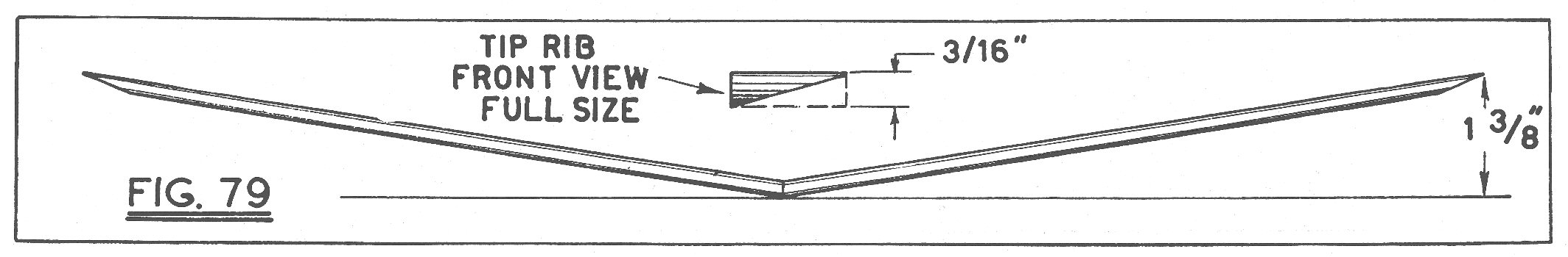
Fig. 78 shows the materialization of these proportions in the form of the glider to be built. The next step in creating our model is to determine its structure; this is governed chiefly by material available. The glider may be made of balsa wood or, if this cannot be obtained, hardwood and paper. All parts can be solid if balsa is used; however, the glider made of solid hardwood would be quite heavy. In this case an assembled frame structure must be worked out. The wing can be composed of leading and trailing edge and spars with ribs between them at intervals along the span; of course these are shaped to give the desired external form: the whole frame can be covered with paper. Stabilizer and fin should be light. To reduce their weight when hardwood is used, cut out the centers as indicated in the plans, then cover both top and bottom with tissue paper. The other main part of the glider is the body or frame stick; this can be solid whether made of balsa or hardwood. However a hollow stick can be made by cementing together two 1/4" wood channels, their flanges being each 1/8". This will produce a 1/4" square hollow hardwood stick. Balsa wood weighs from 5 to 16 lb. per cubic foot, average light balsa is 7 or 8 lb. The best hardwoods to use, evaluated in the order mentioned, are: first, basswood, redwood or cigar box wood (there is very little choice between these); 2nd, whitewood or poplar; 3rd, white pine; 4th, spruce. The evaluation of these woods may be contrary to average opinion but it is based on laboratory tests. White pine should not be used for stressed parts in gliders because it is extremely brittle and though light, it is weak; used as a frame stick it will snap upon the slightest impact. For bulky parts carrying no stresses, like fillets or parts that give form, white pine may be used. In all cases basswood is preferred as it is of uniform grain, comparatively tough for its weight and usually available. Basswood weighs about 30 lb. per cubic foot, about 4 times as much as balsa. Spruce is slightly heavier, 32 lb. per cu. ft., but it is the strongest known wood for its weight and is excellent for stressed parts. It is more difficult to cut than basswood, however, so it is not used commonly; it has a long stringy grain which resists stresses but makes shaping difficult. When building a glider bear in mind that hardwood weighs approximately 4 times as much as balsa, so in order that both hardwood and balsa gliders weigh the same, design the hardwood glider so that only 1/4 of the material is used as in the case of the balsa glider; for instance, in the wing cut away 3/4 of the hulk of the wing. On the plans you will note that the front and rear spar and ribs approximately equal 1/4 of the total volume of the wing itself, so this wing, when made of hardwood, should be approximately the same weight as the balsa wing. This is also true of the stabilizer and rudder. After working out the structural details in a number of sketches draw an accurate set of plans in pencil, similar to the ones shown on page 20. Wing, stabilizer, fin, ribs and irregular parts should be made full size so that they may be used as patterns. A general assembly view drawn either to full or half-scale will show how the plane will appear when finished. Do not start building until you have made a complete set of plans; in this way many mistakes will be avoided and time saved. When you have laid out these plans you will have a complete understanding of the structure and how it is to be put together; the "build as you proceed" method without plans always proves unsatisfactory in the end and it never results in a properly designed or constructed plane. CONSTRUCTION: Now you are ready to construct the plane. First build the wing. If balsa is used shape it to the contour shown in the end view from sheet 2-1/4" wide x 3/16" thick. If balsa is not obtainable use hardwood. First shape the ribs of which there will be 2 center, 8 intermediate, and 2 tip ribs. Only the upper surfaces of the tip ribs are shaped to begin with, the bottom will be shaped later when assembled. When this is done assemble each half-wing by cementing the ribs between the front and rear spar members; do not shape the spars until after they are assembled. Front spar measures 1/8" x 1/4", the rear spar 1/8" x 3/8." The plan view of the wing including dotted lines will indicate how the ribs are to be cemented to these two pieces. Ribs should be cemented in tightly, the cement filling the angles between ribs and spare. Two small "V" shaped fillet pieces 1/8" thick are cemented in the angles between the center ribs and the spars, as shown on the plans. When all joints have dried thoroughly the front and rear spars should be cut away to the cross-hatched cross section shown in the plan view of the wing; the dotted portion is the part cut away. This will provide a carefully streamlined wing section. The bottom of the tip ribs must be cut away on a bevel as indicated in Fig. 79. The lower outer curved edge is cut away so that the underside is flat from the lower inner straight edge to the upper curved edge. The front and rear spars are also bevelled to conform with the under surface of the tip rib. When, both wing halves are finished bevel the center so they fit together tightly when the tips are raised 1-3/8" above the level of the center point, as indicated in Fig. 79. The wing tips may be held at the proper elevation by blocks, books or some other steady means. Cement the two halves tightly together and allow the joint to dry with the tips raised. Next cut out a stabilizer and fin from 1/32" sheet balsa or hardwood. If hardwood is used cut out the centers, as indicated by the dotted line, for lightening. When completed the other parts may be made, namely, the frame stick, 14" long x 1/4" x 1/4"; the wing mount, shown on the plans, and the two fillet pieces. The upper side of the wing mount is notched to conform with the dihedral angle. The front view of the fillets is indicated in the assembly drawing; note the two sides are not at right angles to one another but are slightly more, about 95 degrees, due to the dihedral. When the wing frame is thoroughly dry, cement the wing mount to its center as indicated in the front view. Then make and cement the triangular fillet pieces in place; these provide a strong joint at the wing center and avoid breakage in crashes. Parts may be held together with pins while the cement is drying. When shaping the wing mount note it is deeper at the front end than at the rear; this gives the wing the proper angle of incidence. Be sure to make this carefully so that it conforms to the plans. At the front it should be approximately 1/4" and at the rear, 3/64" less. Then the whole unit is cemented to the top of the frame stick as indicated in the front and side views. The center of the wing should be exactly 5" from the nose of the stick. This joint may be reinforced by binding the two bevelled ends of the wing mount to the stick with several strands of thread; see the side view. Cement the stabilizer to the underside of the frame stick at the rear and the rudder to its right side, as shown in Fig. 78. Now all that remains to be done is add weight to the nose to provide proper flight balance. Cement small pieces of wood, as indicated in the nose-weight detail drawing, to the upper and lower sides of the frame stick on the nose. Then wind several loops of soft annealed wire around the stick within the notches shown. The amount of wire to use may be determined by suspending the model on two fingers at the wing center near the frame stick; the fingers should support the model at a point equal distance from leading to trailing edge. Then cut a length of wire, bend it into a "U" and hook it on the stick at the nose. The model will balance in a horizontal position if the wire is the proper weight. If the nose raises use more wire, if the nose is too heavy cut some away until the exact amount is determined. Then wrap this wire around the stick within the groove and bend in the end with pliers so it will not become loose or detached. Your plane is now ready for flight except for the covering. Of course if balsa is used no covering is required. If made of hardwood cover the wing, stabilizer and fin, top and bottom, with tissue paper, cutting out the paper so there will be 1/8" margin all around the part. Start by covering the lower sides first, half the wing or stabilizer at a time. Cement the paper to the center rib then stretch it spanwise toward the tip, cementing it in place to each rib successively, finally to the tip rib. Then cover the front and rear spars with cement and tack down the paper tightly to them, turning over the 1/8" margin all around the wing. The top is then covered in similar manner. When cementing the paper to the stabilizer and fin be sure not to use too much cement, this increases the weight of the model; only a little is needed on these parts. To tighten the covering spray it lightly with fine water-spray; a fine-spray atomizer may be used. Allow it to dry, keeping the model in an upright position with even support under the wings so they will not warp while the paper is drying. FLYING: Now your model is ready for flight. Test it by gliding it gently with the nose pointed slightly upward. Do not throw it hard at first. If it glides steadily to the ground without nosing up or diving in, the model is correctly balanced; if it noses up or glides in a series of jumps, more weight is needed on the nose; if it dives in and doesn't float gently, less wire weight should be used. Adjust your model carefully until the glide is smooth. Then more extended flights can be made by throwing the glider with considerable force, wings tilted to one side and the nose pointed upward. The method of launching and adjustment for various types of flights is described in article 3, September issue; we suggest you read this carefully. With a little practice long and even out-of-sight flights may be made with this little ship. VICTORY Scanned From March 1943
|