|
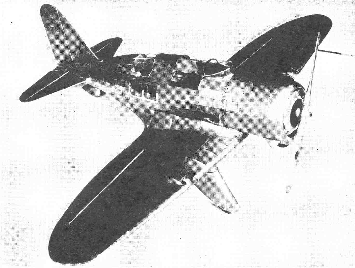
Building the Seversky 3-L by
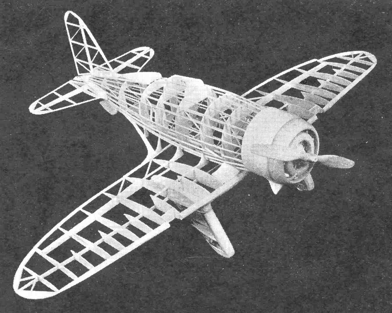
BOTH beauty and speed have been combined in this Seversky model. When painted copper and trimmed in its colorful detail it is the envy of all model builders. Our laboratory tests of this model show: Flights of two to three hundred feet or better. Stability very good. Controls very positive. Speed between 25 and 30 miles per hour. In building your model, follow all steps closely for many improved features are built into each successive model by this department, such as movable control surfaces with aluminum hinges, new and improved method of constructing framework, time proven shock absorbers concealed in landing gears. All dimensions can be quickly and accurately determined by placing a ruler on the part to be measured. The plan is printed full size. If you wish a larger model, multiply this measurement by the amount of increase. Color scheme. Entire ship copper, identification numbers black, "Seversky" on side of fuselage; letters blue with silver streaks in centers, model airplane on side of fuselage; silver, trimmed in black with silver streaks coming from rear, trimmings around cockpits, silver; exhausts and propeller, silver; other small details, black and silver. CONSTRUCTION OF FUSELAGE The fuselage sides are built from 1/16 inch square balsa. The longerons, verticals, diagonal braces, etc., are held in place until securely cemented, by inserting straight pins on either side of strips wherever needed, having first placed wax paper on top of plan, to prevent parts from sticking to plan. After the two sides are completed, the cross-members are cemented into their proper locations. Check carefully from front to rear for alignment. Cut the formers from 1/32 inch sheet balsa and cement in their respective positions as shown on the plan. The balsa ring which fits on front of fuselage, is cut from 1/4 inch thick balsa and cemented together as shown on the plan. After this has been properly shaped and sanded cement to front end of fuselage. Next cut from solid block of balsa rear streamline tip, refer to plan, so that proper shape may be obtained, cement to rear of fuselage. The 1/32x1/16 inch stringers should now be cemented over the formers on the fuselage. The position of stringers are shown clearly on each former. Another fine method of attaching stringers to formers are as follows: Cement top stringer working from front to rear, so that it lines up properly, next apply bottom and two side stringers. We now have four stringers on the fuselage. The other stringers should now be cemented in their respective positions, making sure that they are equally spaced. All stringers are cemented to outer edges of formers, to prevent formers from projecting through fuselage, when same is covered. MOTOR COWLING The front part of cowl is carved and sanded to shape from a balsa block, use a stiff grade of paper for cowl. Before cementing paper to balsa make sure you have the proper fit, overlapping balsa 1/16 inch. DUMMY MOTOR The motor is built up entirely from balsa and sheets of paper. The cylinders are built first, using the sheets of paper cut into disk, etc., to represent the fins. The layers in between these are made of sheet balsa 1/32 inch in thickness. These are cut smaller so as to make the cylinder more realistic. The crankcase should be made from layers of 1/8 inch stock, cemented together and shaped as shown on the plan. A solid block of balsa may be shaped up equally as well. After the cylinders and crankcase have been completed, cement the nine cylinders in their proper locations on the crankcase. The rocker-arm caps and push-rods should be shaped and cemented to the motor. Paint cylinders, crankcase and push-rods black, other small detail, black and silver. LANDING GEAR Select a fairly strong grade of balsa and shape all landing gear parts as shown on plan. After framework of streamline wheel coverings has been built, music wire is formed into shock absorbing axles as shown on plan and cemented to framework with wheels. Sides of wheel coverings may be covered with either tissue or balsa veneer. CONSTRUCTION OF WING Cut all ribs from 1/32 inch sheet balsa. Pin center spar in position on the plan, next cement ribs in their proper locations. The leading and trailing edges are now cut and sanded to shape and cemented to front and rear of ribs. Make wing tips as shown on plan from 1/16 inch sheet balsa. We recommend this type of wing tip, as it is far simpler to construct and neater in appearance. The ailerons are now built into the panels. Ailerons will eliminate the need for building "wash-in" into wing. We recommend that you build your model with all movable controls, as you will need these to control your model under flight. Aluminum hinges are cemented into position after wings, etc., have been covered with tissue. APPLYING WING TO FUSELAGE Leading edge is cut to the proper curve, so that it will fit snugly against bottom stringers. Center spar from Rib A to Rib A is cemented in at a horizontal position. Trailing edge also cemented in a horizontal position. Apply cement to leading and trailing edges and center spar and fasten to bottom side of fuselage. All formers which work from ribs A to fuselage stringers are cemented into position, after first being cut and sanded to shape. Scanned From september 1934
|