|
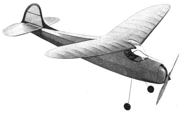
HALF PINT by BILL TYLER DESIGNED ESPECIALLY FOR A. T. READERS,
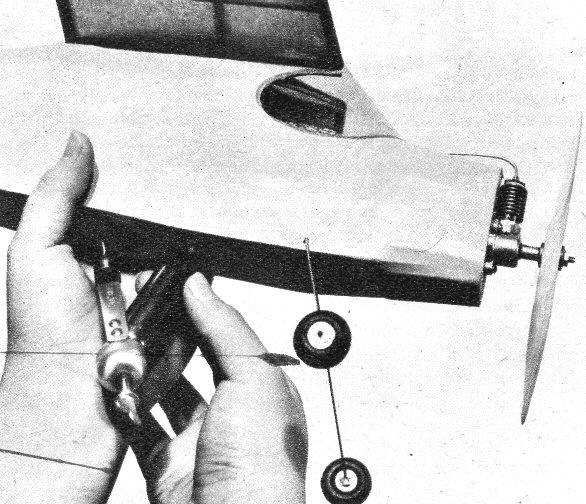
At last, a gas model that can literally Be carried around in a hat box. Furthermore, it's really the first gas model in the true meaning of the word, as carbon dioxide, the engine "fuel" is a gas and not a liquid as is used in the conventional type of gas model engine. The peanut-size Herkimer CO2 engine. which we used for the first time on this model, is not a two-cycle internal combustion engine, nor call it be called a diesel or compression ignition type. Engineers would term it an "expansion-type reciprocating engine" as it is the energy of the expanding carbon dioxide gas that provides the power for turning over the crankshaft. Don't be fooled by the small size of this engine. While the overall height is only 1-3/4" and the displacement is but .0178 cubic inches compared to .099 cubic inches --- the displacement of the current smallest Class A engines --- the little CO2'er really gives out with much power. Strobotac tests have clocked it at over 7,000 r.p.m. using a 7"-diameter 3"-pitch prop. It has power plus, and will successfully fly models up to 40" wingspans with wing areas of 140 square inches. For the experimental-minded modeler, the CO2 engine offers all kinds of possibilities. Because of its consistent performance (each cartridge contains the same charge of gas) many interesting tests can be conducted. By using the same prop for all experiments, accurate comparative tests can be made on different type airfoils, fuselages. etc. The small size of this engine lends itself beautifully to completely incloseed cowlings as you don't have to allow for cooling or air intake openings. For radically designed models, the ones you always sketch on paper but never dare build. the C02 engine is the answer. Flying wings, pushers, canards, or what have you, can be fully exploited in a small economical size before time and supplies are wasted on large "full-scale" models. This procedure can even be followed by builders of large six-foot Class C models; a half size CO2 powered model can be made of a new design and fully developed in small size before building the big brother. This method of testing is done on real aircraft and now can be done with CO2 powered models to eliminate design and structural defects before going full-size. It was in line with the above thinking of testing a new proposed design in a smaller size before building the full-scale ship that Half Pint (the full-size model is called Full Pint--that's a pun, chum) was built. We wanted to test our latest Class B brainstorm that had a wingspan of 56", so in laying out Half Pint for the CO2 engine, we made the wingspan exactly 28" and scaled our full-size plans to one-half the original size. Buddy, we found that this new method of testing a "model of the model" really works. Half Pint, with a few minor adjustments, amazed us with its flying ability and will amaze you too. You will be more amazed at how easily and quickly yon can build a model of this size. It is no more complicated than a simple, rubber-powered model. The plans shown here are exactly half size and can easily be duplicated full size by simply multiplying any dimension by two. A scale is shown on the drawing and all curved sections are "gridded" for your convenience. The fuselage is built around a basic square framework of 1/8" square stringers and is completed by adding the turtledeck structure and nose faring. Note that the under section of the fuselage, where the cartridge holder is located, is sheeted with 1/8" soft balsa and a hole is cut in this section to house the holder. Finish off the fuselage by adding the firewall which is built up from two 1/32" ply wood faces and 1/8 " balsa core. Before adding the firewall to the fuselage structure, locate the mounting holes and attach the motor using #3 round head bolts. Now carve the cowl from a solid block of soft balsa and hollow the inside to house the motor. Dress snaps can be used to make the cowling detachable. Locate the cartridge holder within the fuselage before covering and try to avoid any sharp bends in the copper tubing that might cause an unsteady flow of gas while the engine is in operation. The landing gear is bent front 1/16" piano wire and cemented securely to a 1/32" plywood sheet backed up by a sheet gusset. All landing gear dimensions can be obtained from the drawing by using the enlarging scale. The tail surfaces are cut from 1/8" cut balsa and follow standard gas model construction. In assembly. the stabilizer must be cemented to the fuselage first and then the rudder placed in position. Cement all joints of both the rudder and stabilizer securely to prevent warpage. The wing was built by what we call the "quickie" process. Instead of plotting out a lot of ribs as is usually required in making a tapered wing, we used a method that was introduced to outdoor modelers by indoor builders: A wing rib template is cut from thin sheet aluminum or tin the width of the maximum wing chord. Using this template as a guide, a series of top ribs are sliced from sheet balsa. On a model of this size, the top ribs were cut from 1/16" sheet balsa by 3/32" deep. Lay these ribs aside and now form the wing spar. Place strips of 1/32" x 3/32" balsa on your wing drawing at each wing location and pin in position. This forms the bottom part of the wing ribs. Cement the wing spar in place. Add leading and trailing edges, then the tips. Once this is done the upper part of the rib can be added over the top of the wing spar. When this wing half is dry it can be removed from the drawing board and the other half wing constructed. The center section is added last. This method of construction is much faster than cutting out tapered ribs and is very easy to do once the knack of slicing ribs with a template is mastered. The windshield is cut from .016 celluloid sheet using the half pattern shown on the plan as a template. Once the wing has been cemented to the fuselage the windshield can be added in position. It is best to attach it first to the center section of the wing, then to the nose of the fuselage and dually to the sides. Masking tape may be used to hold the celluloid in place while drying. The original model was covered with light Silkspan and the fuselage doped yellow while the wing and tail surfaces were colored green. To keep weight to a minimum we dyed the Silkspan used on the wing and tail surfaces by dipping the tissue in a solution of green analine dye and water. Remember, Silkspan can be worked wet. Analine dyes can be obtained in most local drug stores. Before test flying your model, check carefully to see that all surfaces are free from warps and are properly aligned. Check to see that the center of gravity is located at approximately the same point as the wing spar. Next, try a couple of glide tests and make any minor adjustments necessary for proper balance. Don't forget that a cartridge should be placed in the cartridge holder and that a prop should be attached to the engine during these preliminary tests. (The cartridge holder is held in the fuselage by an elastic band attached to two small hooks on the bottom of the fuselage.) When you are satisfied that the model is in flying balance then try a test flight. Do not use the full cartridge charge on this test flight but allow at least the maximum power portion of the engine run to be exhausted before hand launching the model. You may find that the model will tend to stall under power: if so, a small amount of down thrust should be added before flying the model with the engine wide open. You may be sure the Half Pint will give you a barrel of full! Scanned From August 1947
|