|
A Flying Twin Motor DOUGLAS DB-7 A Realistic Model Bomber. This Is Easy to By SIDNEY STRUHL
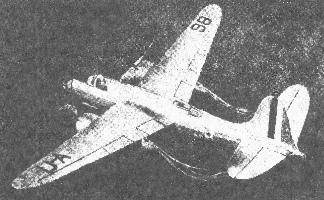
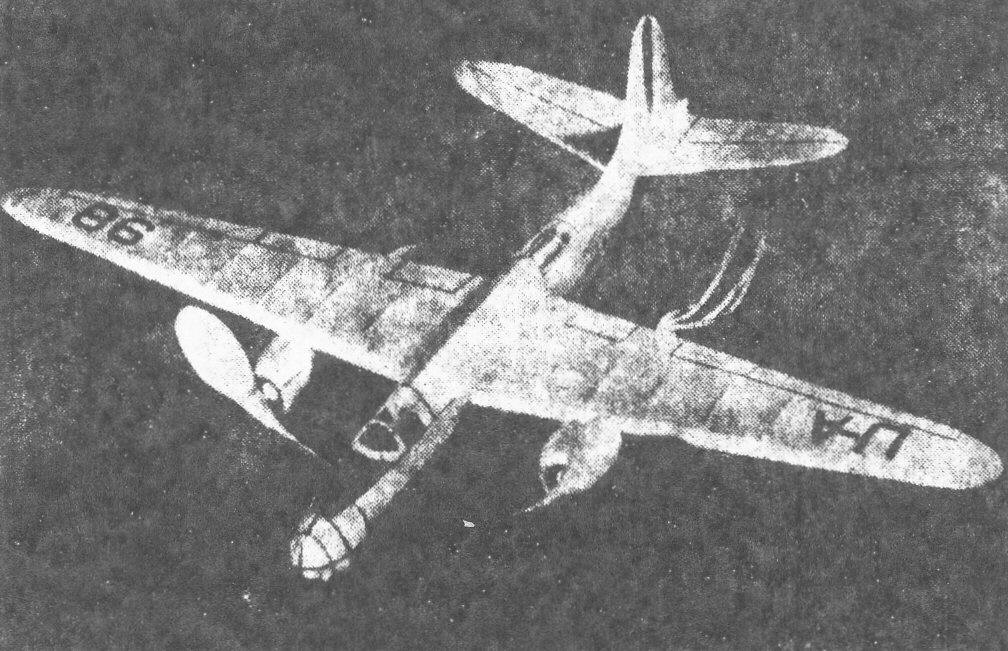
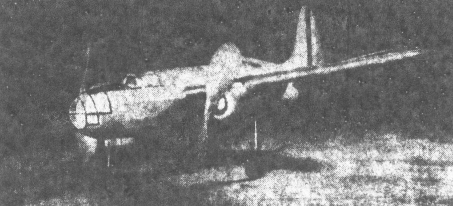
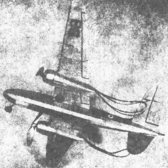
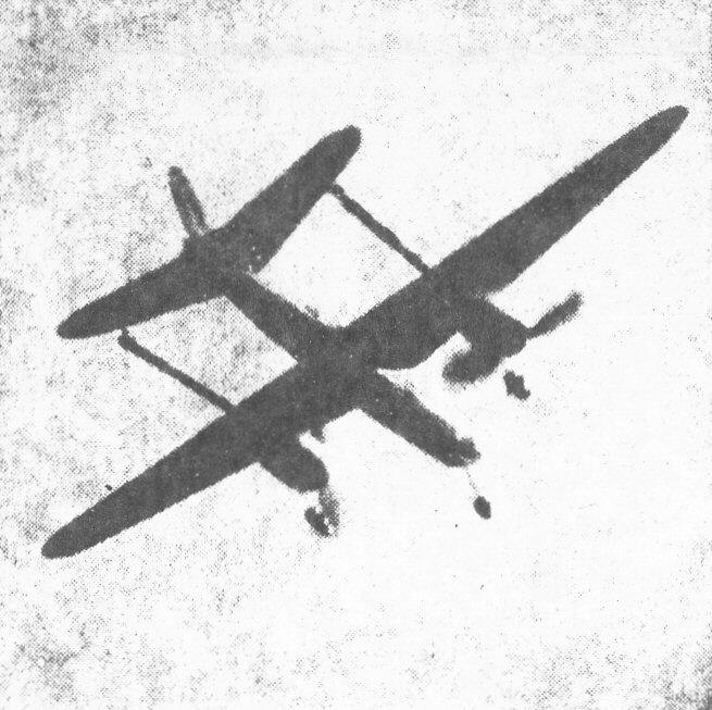
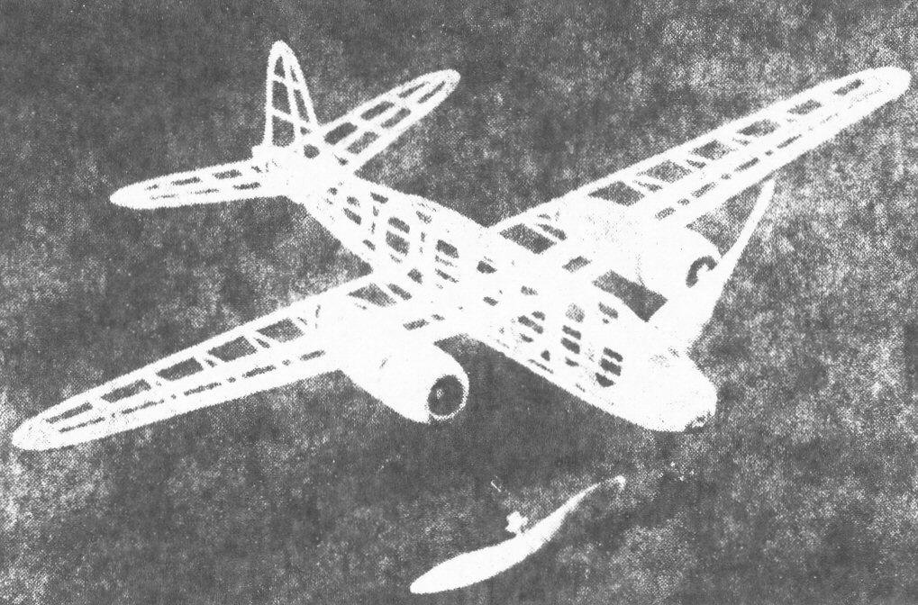
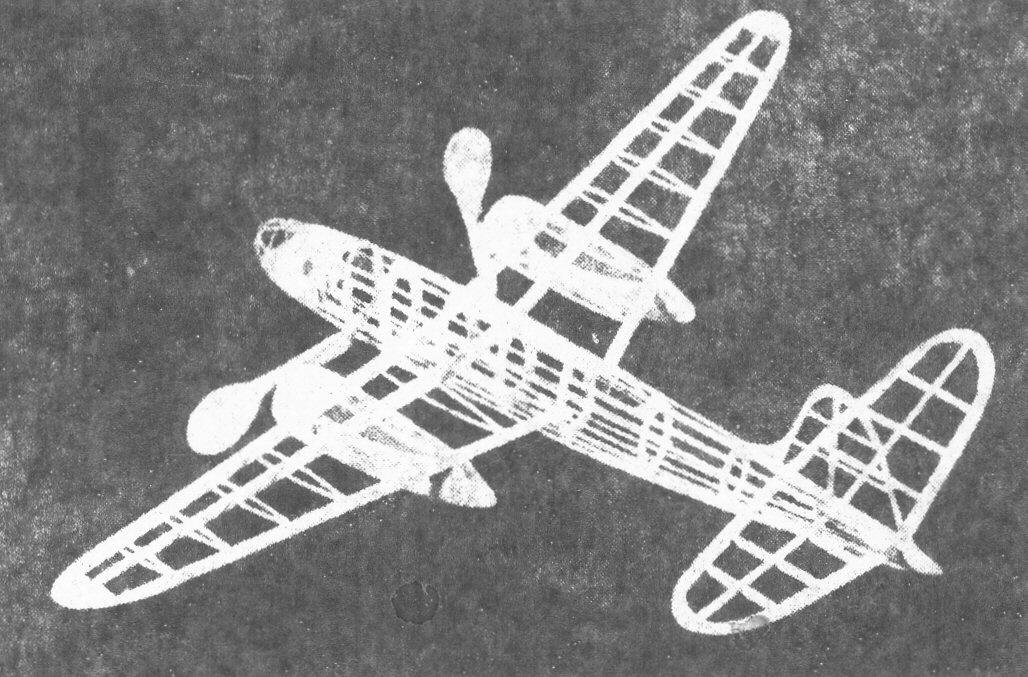
WE ARE presenting this month, as our flying scale feature, the startling new Douglas Attack Bomber DB-7. The Douglas DB-7 is a twin-engined all metal monoplane high speed attack bomber, with many ad vanced design features incorporated into it; such as dihedral in the stabilizer and tri-cycle landing gear. This plane was originally designed and manufactured for the French Government. However, due to the terrible and swift "blitzkrieg" of the Nazis, France capitulated in a very short time, and very few ever got to France. At present production is going ahead on schedule on the original French order, but the purchaser is not France but Great Britain. This is borne out by the fact that Douglas DB-7's are arriving at Floyd Bennett Field for shipment to England, by way of tramp steamer. The Douglas DB-7 is called the "Boston Bomber" by the British. Power is supplied by two Pratt & Whitney SGR-1830-SC3-G "Twin Wasp Seniors" developing 660 horsepower for cruising, 910 horsepower for climbing and 1065 horsepower for take-off. The motors drive Hamilton Standard Full Feathering Autoainatic Controllable Pitch propellers of 12 feet diameter. The DB-7 has a wing spread of 61 feet, 4 inches and is 46 feet long. Gross weight is 16,280 pounds. 2350 pounds of bombs may be carried. The top speed is 349 miles per hour and the cruising speed is 312 miles per hour. While the landing speed of 72 m.p.h. may seem high, it must be kept in mind that, with a tricycle landing gear, landing gear speeds of 120 m.p.h. are perfectly safe. The United States Army Air Corps has given the Douglas company a $25,000,000 order for a slightly modified version of the DB-7, to be known as the Douglas A-20 and the A-20A. After closely studying this ship you will find that it very admirably lends itself to a flying scale model. The general set-up of the job though quite speedy, has remarkable stability; due to the large tail surfaces and dihedral in the stabilizer. Even with the dihederal in the stabilizer, there is not the slightest tendency for the model to rock during flight. The two high-pitch props pull the plane up in a climb that would put the "big job" to shame! The props rotate in opposite directions to eliminate torque. Careful construction and design have kept the weight down to a mere two ounces. Now let's get down to actually constructing the Douglas Attack Bomber DB-7. Fuselage In constructing a fuselage such as this one it is best to use the half-shell niethod. First attach the fuselage drawings so that they line up perfectly. Before going any further, we should say that all the wood used in the construction of the DB-7 should be of the lightest grade obtainable. That does not mean the soft spongy grade. First cut out all fuselage bulkheads from 1/16" sheet balsa. Only half the bulkheads are shown on the plans, thus it will be necessary to make two each of those shown. Bulkheads B, C, D, E and F are all the same shape, so you make 10 caf these. Pin the bulkheads in their proper positions on the plans, making sure that they are at right angles to the working surfaces. Now pin the 1/16" square hard balsa stringers in place directly on top of the bulkheads and cement them very securely. Trim the ends of the stringers flush with Bulkhead A-A. Note that one stringer ends at Bulkhead H-H and one at I-I. After the cement has set on the framework remove the framework and glue the other half of the bulkheads to their respective first halves. Add the stringers to this side of the fuselage. Shape the tail block from 3/16" sheet balsa and glue in place, bringing the rear of the fuselage stringers flush with its edges. Shape the nose block front a soft balsa block and cement in place. The bamboo framework should be bent and shaped from 1/32" square strip, and glued in place; the design is shown in the plans. The pilot's inclosure and rear gunner's cockpit is made in the same way. These may now be covered with thin celluloid. The nose will require small pieces of celluloid because of the compound curve there. Bend the front landing gear strut front .038 music wire to the shape shown in plans, insert a celluloid 5/8" diameter wheel in place and then cement it with several coats to the rear of bulkhead A-A. A small piece of balsa is cemented behind bulkhead A-A to help shape the front of the pilot's cockpit. Wing Space permits us to show only one half of the wing. You will have to trace and then invert the wing plan shown to get the left wing panel. Make a cardboard template of the wing rib at the root. With this template slice from 1/16" quarter-grained sheet 18 upper ribs of l/16" square and 18 lower ribs of 1/16" square. Shape the leading edge from 1/4" sheet and the trailing edge from 1/8" sheet and pin them in place. The trailing edge will have to be blocked up 1/8" to fit in the airfoil contour. Now glue the top ribs in place, but to the leading edge only. After the cement has set trim the trailing edges of the ribs so they fit to the trailing edge. After the cement has set well, remove the wing from the plan and attach the lower parts of the ribs in the same manner. Cut the wing spar from 1/16" sheet to the shape shown by the dotted lines in the plans; slip the spar in place through the ribs, cementing each rib to it. The wing tip is shaped from a solid piece of 1/16" sheet balsa. The ends of the leading edge and wing spars should he cut to the required angle so that they fit together inside the fuselage with necessary dihedral angle of 1-1/2" under each wing tip. The wing should be glued in place before it is covered. You will note in the side view that the wing position is given very clearly. Motor Nacelles The two motor nacelles are shaped from solid, very light and soft balsa and then hollowed to the necessary thickness. Two balsa blocks 1-1/2" x 1-1/2" x 5-1/2" will be required. First trace the top view onto the blocks, then shape with a sharp knife. Trace the side view onto the block and shape. The nacelle is then trimmed with a razor to the required cross section. Finish the job with fine sandpaper. Now split the nacelle down the top so that you will have two sides. Hollow these two halves with a knife, razor, and sandpaper till the walls are about 3/64" thick in the center and slightly thicker at the front, as shown in the plans. The two hollowed-out halves may now be cemented back together again; giving them two coats of clear dope. Sand with 10-nought sandpaper. Cut out the two nacelle bulkheads from hard 1/8" sheet balsa, drill a hole for the nose bearing and then cement in place. Bend the landing gear struts from .038 music wire bo the required shape shown in the plans and cement the strut very firmly to the nacelle. You will note that the wire runs through the floor of the nacelle, along the floor and then half-way up the side for added security. Either balsa or celluloid wheels of 1-1/8" diameter are held on the axles by a drop of glue at the end of the wire. The finished nacelles are not cemented in place on the wings until the wings are completely covered. Tail Surfaces The tail surfaces are very easy to construct; the rudder is built from all 1/16" flat stock. The spars are 1/16" x 1/8" strips and the ribs are 1/16" square strips. The tip is cut front 1/16" sheet balsa. Pin all the members in place and cement them carefully. Make sure when yon remove the rudder from the plans that there is no warp; if there is, steam it back to shape. The stabilizer is built in the same manner as the rudder, with the exception that all the stock used in the stabilizer should be 1/8" flat. You. need a strong stabilizer because it has to carry the load of two motors on it. The stabilizer has 1" dihedral at each tip. Bend two rear hooks from .034 music wire and cement them to the last outer ribs at the stabilizer tips. The, hooks are glued to the bottorn of the stabilizer, by the way, and not the top. Propellers Two propellers are required. They should be carved so that one is right-banded pitch and the other left-handed pitch, "to do away with" torque and thus save you a major adjustment problem. The props are of rather high pitch for a flying scale, but they give a marvelous performance. The blocks are 3/4" x 1" x 5" and should be shaped to the blank shown in the plans. The wood may be light grade because you need have no fear of broken props on this job; the tricycle landing gear and the propeller positions take care of that. The props should be covered in the conventional way, with the hubs about 1/8" thick and the tips tapered to 1/32" in thickness. Two prop shafts of .034 wire are bent to shape, slipped through the hardwood nose bearing, a few copper washers and then inserted into the prop hub, bent at right angles and cemented to the prop. Give the prop hubs several coats of cement just to "make sure." The two props are now treated with clear dope in the same manner the nacelles were. Covering The author covered his DB-7 with the new Silkspan; regular tissue paper may be used however. The stabilizer should be attached to the fuselage before it is covered. Trim a piece of covering to the shape of the fuselage, wet it thoroughly with water then place it on the fuselage and smooth out all the wrinkles. Then run clear dope over the extremities. The dope will penetrate and act as a good adhesive. Repeat for covering the other side of the fuselage. The wing is covered in the same way but extreme care must be used at the fuselage and wing joint to insure a good and clean job. Separate pieces must be used to cover the wing tips. Cover the rudder and stabilizer in the same manner as the wing. After the covering and dope have dried, spray on a coat of water to tighten any loose spots. After the water dries apply one thin coat of clear dope with a brush. When the clear dope bas dried apply two very thin coats of silver dope to give that aluminum finish; use just enough silver dope to give the job a solid color; for while silver is the lightest of colored dopes, nevertheless too hunch will add unnecessary weight to model. All of the exposed wood parts, as the props and nacelles, are also given two coats of silver dope. All details, such as the elevators, fin and flaps, are shown by doping thin strips of black tissue paper to the surfaces. Either British or French insignia may be applied. The inside of the motor cowls are painted black. Flying Each prop of your DB-7 should be turned by four strands of 1/8" flat brown rubber. Two "S" hooks will be needed to attach the rubbers to the rear hooks. Attach the rubber motors to the S hooks, drop the hook through the opening in the nacelle bulkhead, through the nacelle and out of the small hole at the rear of the nacelle. Then connect the S hook to the rear hook. The prop shafts are now slipped on the motors. Flying your plane is definitely a two-man job; you will need a helper to hold the ship by the props while you wind the ship with a double winder. Another reason for using props of opposite pitch is because all double winders turn in opposite directions. Before any flights are made test your ship for the gliding angle by gliding it over some tall grass. The author had to add a little modeling clay to the nose for perfect balance; you will probably need to do the same, due to the weight of the motors being so far back. Now that you are ready for your first flight have your helper hold the ship by the props, then attach the S hooks to the winder and give the motors about 75 turns for a test flight. Your ship should climb a bit then settle in a long glide and come in for a perfect landing. If any adjustment is needed at this point do so by changing the angle in the stabilizer. The model should balance right on the rear landing gear strut mark. When fully wound, the DB-7 takes off like no bomber ever did and climbs at an amazing angle. Some of you old timers who can still remember the climb on the old twin-pushers know what we mean. After the power is spent, your model will go into a very flat and fast glide. The landings are a treat to see; the ship just seems to slide in on its three wheels. Well, we won't say any more except, you build the ship and just wait and see!
Scanned From March 1941
|
||||||||