|
Indoor Autogiro An experimental model of value to both By Lawrence N. Smithline
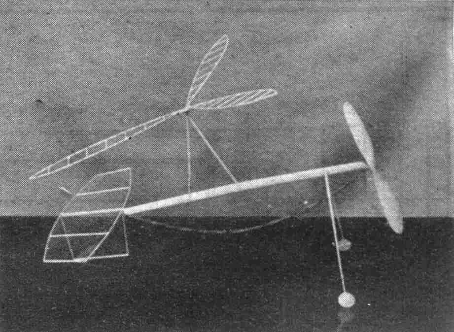
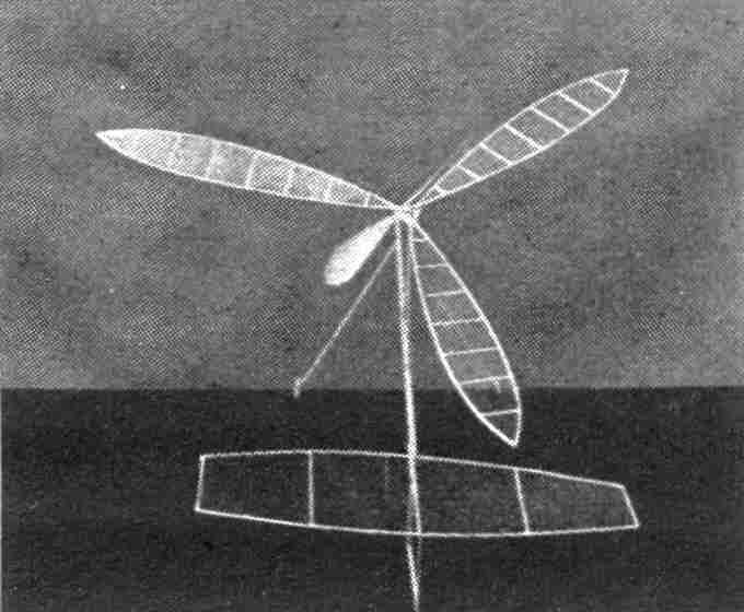
THE AUTOGIRO is the model builder's orphan child. It has been neglected because it is such an inefficient means of flight and because it does not glide, thus making its chances of high duration very remote. The wingless autogiro, although very successful in full-sized craft has, except in a few cases, defied model builders. The secret of wingless autogiros is patience. Only after many hours of experimentation were the kinks of this model ironed out so that it could be termed successful. The model was designed primarily so that it would stand abuse, as it was realized that it would have many an unfortunate experience before it would be adjusted. Weight, therefore, was a minor consideration. VANES The rotor of this model was made three-bladed for simplicity. A fourth blade may be added. In fact, it would probably be easier to adjust a Model with four blades instead of three. So if yon are of an experimental turn of mind make a fourth blade. Make a drawing of the outline of the blade and pin 2 strips of 1/32" square medium balsa to the drawing. Cement in the ribs, which are likewise 1/32" sq. and without camber. Make the other blades in the same way and then cover them all with microfilm. Make the hub of 1/32" sheet balsa laminated as shown, and cement the bearing, which is a washer on either side of the hub, in place. Cement the blades in place. Raise the outside tip of each vane 1/2" and the trailing edge at the third rib from the end 5/32". The result should be a negative incidence. This is very important. TAIL AND RUDDER The tail is made of 3/64" square soft balsa which has been pinned to a full sized drawing. The center rib is flat and the other ribs are slightly cambered. Looking toward the propeller the ribs on the left are conventionally cambered, whereas those on the right are reverse cambered. This is done to give an even greater rolling moment, to overcome the torque, than is possible from a flat tail alone. The rudder is made very simply of 3/64" square balsa and is cemented underneath to keep it out of the way of the vanes and also to bring the C. G. of the model as low as possible. MOTOR STICK, LANDING GEAR, AND VANE BIPOD The motor stick is hollow and made in the conventional way for indoor models. It is 12" long and made from a blank 1" at the center tapered to 3/4" at the ends. The blank is 1/32" light sheet balsa. Soak the blank in hot water, bend and bind it around a former 3/8" by 1/8" at the center, tapered to 1/4" by 1/8" at the ends, by l2" long. Allow it to dry. After it is dry cement the seam, angle the front end, and cement the caps on front and rear. Cement the dural thrust bearing and rear hook in place. Make the landing gear from medium balsa to the size shown on the drawing. Cement the axles in place and put on the wheels. Keep the wheels on with a drop of cement at the end of each axle. The bipod is made of medium balsa 1/8" by 1/16", corners rounded. Then angle one end of each stick and cement them together, so that they form a "V" of the dimensions shown. Make a shaft, cement it and put on a washer. We are now ready to make the propeller. PROPELLER The 7" diameter propeller is carved from a light block
7" by 1/2" by 1-1/8". Such a propeller is used as a low torque is desired.
Draw diagonals on the wide faces of the blank. Cut down to the diagonals,
then carve the propeller in the conventional way, starting with the
concave side of each blade first. Finish and sand the concave side before
even starting the convex side. After finishing the convex side cut out the
template of the blade shape, pin it to the blades one at a time, and cut
the blades to fit the template. Finish the propeller ASSEMBLY Cement the tail assembly on the rear end of the motor stick. The tail should be at a negative angle, as shown in the drawing. Cement the landing gear in place and allow it to dry. Insert the shaft of the propeller in the thrust bearing and put a loop of 5/64" rubber 13" long in place. Now balance the ship without the rotor and bipod. The center of the bipod should be located over the point of balance. Slice the seam of the motor stick about 1/2" long just about where each leg of the bipod should be. Insert each into its corresponding slit till they touch the other side of the motor stick and cement up the slit. Make sure you have the correct incidence in the plane of the vanes (about 5°). If, after the cement has dried, the bipod is flexible at the point of insertion of the legs, brace it with a strip of 3/64" sq. balsa. Now find the approximate vertical position of the C. G. (keep the rubber on the motor stick for this test, in order to simulate flying conditions as much as possible.) Then bend the thrust bearing so that the thrust line passes through this point. ADJUSTING AND FLYING First see that the vanes rotate freely. Then, holding the model above your head, vines parallel to the floor, rotate them slowly with your other hand and let the model drop. The model should come straight down or move forward only a short distance. It should not have rotated with the vanes any more than 1/8 of a turn in a 6-fool fall. If it did the friction of the vane bearings is too great. Relieve it before going any further with the tests. The launching procedure is as follows: Wind the rubber about one of knots. Then, holding the model above your head, draw it down vertically and forward so that the vanes rotate and release it. At the moment of release the plane of the vanes should be parallel to the ground. The model will probably spiral into the floor because of the torque of the propeller. To overcome this treat the tail as a wing -- put washin in the left side, washout in the right. Another trick that might be used is bending the rudder to make the model turn against the torque. This should eventually get the model to fly correctly. If you still cannot get the model to fly well you might, as a last resort, make a simple auxiliary wing 15" long and 1-1/2" wide, which call be washed in to overcome the torque. Scanned From September, 1943 |

