|
AIR YOUTH GLIDER N0.2 A WELCOME CLASS PROJECT IS THIS PROFILE-TYPE
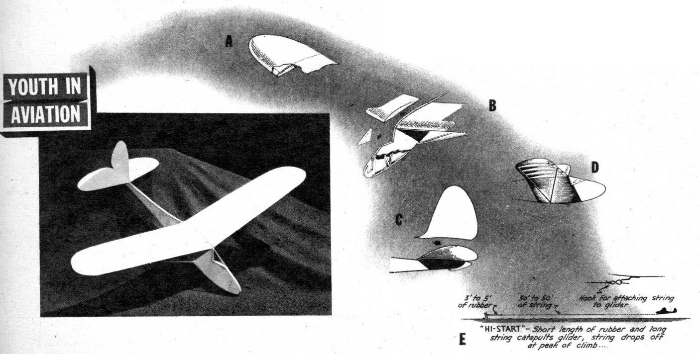
THE second project in this series of classroom designs has a more authentic resemblance to full-scale gliders, though it retains the simple construction of the first hand-launched project because of the easy-to-build profile-type fuselage. Two-ply Bristol board and pine replace the usual balsa-and-tissue construction, but the additional weight does not handicap performance. The plans are reproduced in full size. Make accurate tissue patterns of all surfaces; then, using carbon paper, transfer all surface outlines onto ordinary two-ply Bristol board (obtainable in any art supply store). Use shears to cut out these outlines. Remember that there are two sides to the fuselage and two wing panels. Now cement the pine framework in place as shown by the plan, using plenty of cement on all joints to assure adequate strength. When thoroughly dry, cement the other fuselage side in place, and complete by adding the cockpit cover (Cellophane from a cigarette package) and tow-line hook (an ordinary paper clip). For details of fuselage construction see Fig. B. The wings are made by bending back the additional area shown on the leading edge of the wing and cementing it in place; this serves to reinforce the wing structure. Using 1/16" pine, cut out the wing ribs from the full-size templates and cement into their proper locations as shown on the drawings. Use straight pins to hold the Bristol board in position during this procedure; Scotch tape is handy for holding the edges in place. Note that the end rib (A) is set with a slight bevel to correspond with the one-inch dihedral angle. Figs. A and B illustrate wing construction. While the wings are drying, cement the stabilizer into position on the fuselage. Note that the fuselage has, at the point of attachment a convex contour, which is transferred to the stabilizer (giving rigidity) when the latter is cemented in place. See Fig. C. If this does not stiffen the stabilizer sufficiently, fashion two pine struts from 1/16" pine, cementing one end of each strut to the bottom of the stabilizer and the other end to the bottom of the fuselage. After the stabilizer has dried thoroughly, add the rudder, taking care that it is cemented in line with the fuselage when viewed from the top of the fuselage and along the front. Again. if the rudder seems too flexible, correct by attaching pine struts from the middle of the rudder to the stabilizer. The grade of Bristol board used will determine the necessity for using struts. Cement one wing panel in position and add the two pine struts (Fig. D). While this is drying, sight along the leading edge of the wing to make certain the wing panel is not warped; any such warping may be corrected by adjusting the struts at the point where they attach to the wing. Complete the model by adding the other wing panel. The model should balance at a point approximately one third of the distance back from the leading edge of the wing. To obtain this adjustment, weight (solder scraps are ideal) must be added to the nose of the model. Now try gently launching the model from the hand to the ground. If the model stalls, more weight should be added to the nose until an even glide results. If it seems nose heavy, part of the weight must be removed; experiment with several trial glides to get the correct balance. If the model tends to be heavy in either wing, correct by slightly bending down the trailing edge of the heavy wing. After these preliminary adjustments, thrilling flights can be made by using a catapult launching method. Drive into the ground a stake to which is attached a short length of 1/8" rubber band tied to about thirty feet of string. See Fig. E. Tie a small wire ring, fashioned from a paper clip, to the end of the string. Place this loop over the hook on the bottom of the model, walk backward several steps, then release the model and she'll zoom up to an altitude of about thirty feet at which point the string falls off and she's on her own. Scanned From May, 1943
|