|
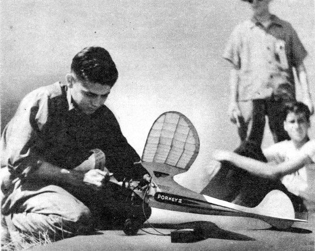
PORKEY By Eldred Hoopengarner YOU'LL NEED A SURE-FIRE CONTEST DESIGN FOR SUMMER
COMPETITIONS.
PORKEY has become almost a model tradition around Cleveland. Even her "son," Corkey, built over the same design, has turned in almost perfect performances. When she leaves your hands, she goes right up, and leveling off into a beautiful, flat glide, she is reluctant to come down. Make a full-sized outline drawing of the top view of the fuselage, using the dimensions given on the side view. Cut out the fuselage formers and notch them as shown in Plate 2; notice that former C is cut from 1/8" sheet. Use the formers for measuring the width of each station. From this layout, mark on the 1/8"-sq. longerons the location of each former. Now cement the formers into place. starting at the front and working toward the rear. The longerons at the rear of the fuselage are tapered so that the finished width is 1/8". Check frequently to make sure that they have not dried crookedly. Now cement the top and bottom longerons into place, working from front to rear. The top longerons, two pieces of 1/8" sq. between formers C and G. are spaced 3/64" apart to receive the pylon stiffener. In doing this, be sure to keep the horizontal longerons straight. The inside planking, used for the ignition-unit housing, is of 1/32" sheet stock. The full-sized templates on Plate 2 show how the four separate pieces are installed. Two pieces of balsa 5/16" sq. x 7/8" long, are notched in back and bottom for wire part Y. Cement them to the fuselage with the wire hook in place. These blocks are flush with the longerons upon which they are cemented. The outline pieces of the rudder, stabilizer and wing are drawn out in the full size and used as templates. First rule off a sheet of paper into half-inch squares, with the same number of squares as shown in the drawing. Now reproduce the surfaces into the full-sized squared paper. These drawings can be used not only for templates, but also to build the parts upon. The tail skid is laminated as shown and cemented into place. The pylon stiffener is cut froth 3/64" three-ply aircraft plywood. Two pieces of 1/32" flat bass or balsa cemented together with the grain at right angles may be used as a substitute if the plywood is not available. Cement this into place. Now cement 1/8" sheet to both sides with the grain running as shown by the dotted line on the pylon-stiffener template. Two wire hooks bent from 1/16" music wire fit into the slots; let a half inch project from the edge of the stiffener. The wing platform is cut from 1/16" sheet with the grain running with the span of the wing. The front part of the platform can be easily shaped by soaking the balsa wood in water for a few minutes and then wrapping it around a 3/8" -diameter wood dowel. A strip of cloth about a half-inch wide is wrapped around it and left to dry for about twelve hours When dry, glue in place, being sure to get it perpendicular with the pylon. The pylon fairing is carved from extremely soft balsa. If desired. the fairing may be formed by covering with silk, although it is much more difficult to do. A 1/8"-diameter maple dowel 1-3/4" long is attached to the front face of former O. The fuselage is planked with 1/32" sheet stock put on in four or more separate pieces. If desired. stringers may be added between the four 1/8"-sq. longerons and the plane covered with either bamboo or Silkspan paper. Cut former B from 1/32" plywood and attach it to the front of fuselage. Bulkhead A (firewall) is cut from 1/8" three-ply wood. Hold the firewall against the fuselage and drill two holes on the outside of motor mounts, 1/8" in diameter x 1" deep. Remove the firewall and cement two 1/8"-diameter maple dowels 1-1/16" long in place. Sand the projecting end round so the firewall can be slipped easily into place. Drill the rest of the holes in the firewall. Give several coats of lacquer to prevent oil from soaking into the wood. If it is desired to leave the plywood natural, give several coats of varnish, which will last much longer than the lacquer. The landing gear is bent to shape from 3/32" diameter music wire. The metal clips V and W are shown in full size. Use # 4-40 machine screws for landing gear attachment. Bend wire hook X as described and attach to motor mounts. The outlines of the stabilizer should be cut from the required thickness of sheet materials. Pin the 1/8 "-sq. spar in place and cement the outline pieces and leading edge together. Cement, the ribs (pieces of 3/8" wide by the desired length) into place. The ribs should now be trimmed with a sharp knife and sanded to conform with the typical stabilizer rib shown on Plate 2. Cement the two 1/16"-sq. top spars in place. Sand the leading and trailing edges to shape. The rudder is constructed in the same manner as the stabilizer except that the ribs are 1/32" sq. and do not conform to an airfoil shape. Part N is assembled to rudder at this time. Cut out former M and attach to part N. Cement the rudder and stabilizer units together. Now for the wings. One of the best procedures is to start with the spars. On Plate l, at the bottom, is the front view of the wing. Draw the bottom line full size to construct the spars upon. The spar sizes are given along with the joints at the center section of the front spar. The rest of the joints are made in the same manner. Leave the spars long enough to insure a good joint at the wing outline. While the spars are drying, cut out the tip outlines and glue them together. All of the ribs are given in full size. Cut out the required number from 1/16" sheet of medium-hard-grade balsa. After the spars are completed, mark the location of each rib to facilitate assembly. The ribs are slipped onto the spars, starting from the center and working out. Glue in place as you go along. The ribs are at right angles to the spars at all points. After the ribs are in place, pin the assembly on the drawing. The leading and trailing edges are glued in place, followed by the tips. Add the 1/16" x 1/8" top spars and sand to shape. Now add the 1/32" sheet covering on top and bottom between ribs 1 and 2. This forms the wing rest on the bottom and prevents the rubber bands from going through the covering on top. The ignition system is clearly shown on the drawing (Plate 3). The timer is not fastened permanently until proper flight adjustments have been made after a few flights. The original model balanced with the coil, batteries and timer in the position shown. The U-shaped piece of music wire at the front of the track is embedded in the wood, wrapped with thread and doped. The model should balance, when completed and ready to fly, at one half of the wing chord. Glide the model several times over tall grass to check the balance. It should be tested until it has a long, flat glide. Now comes the real thing - testing the model, under power! First you offset the motor about one degree toward the right, and place a 1/32" flat washer under the rear mounting bolt of the motor for downthrust. Turn the rudder slightly so that the plane will make large circles to the right in the glide. Next test your motor and adjust it to run at low speed without sputtering or cutting. Start your motor, set it at about one-third speed, set your timer for approximately ten seconds and throw the ship, with only a little harder shove than when gliding, gently into the wind. The ship should turn very slightly toward the right under this power, but it will straighten out and finally turn toward the left as more power is given. Scanned From April, 1943
|