|
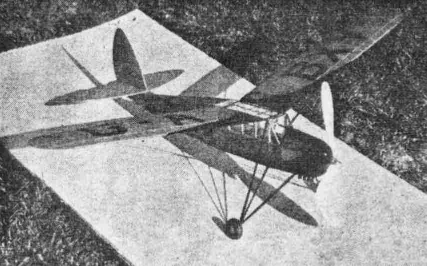
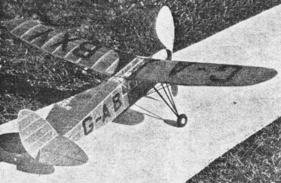
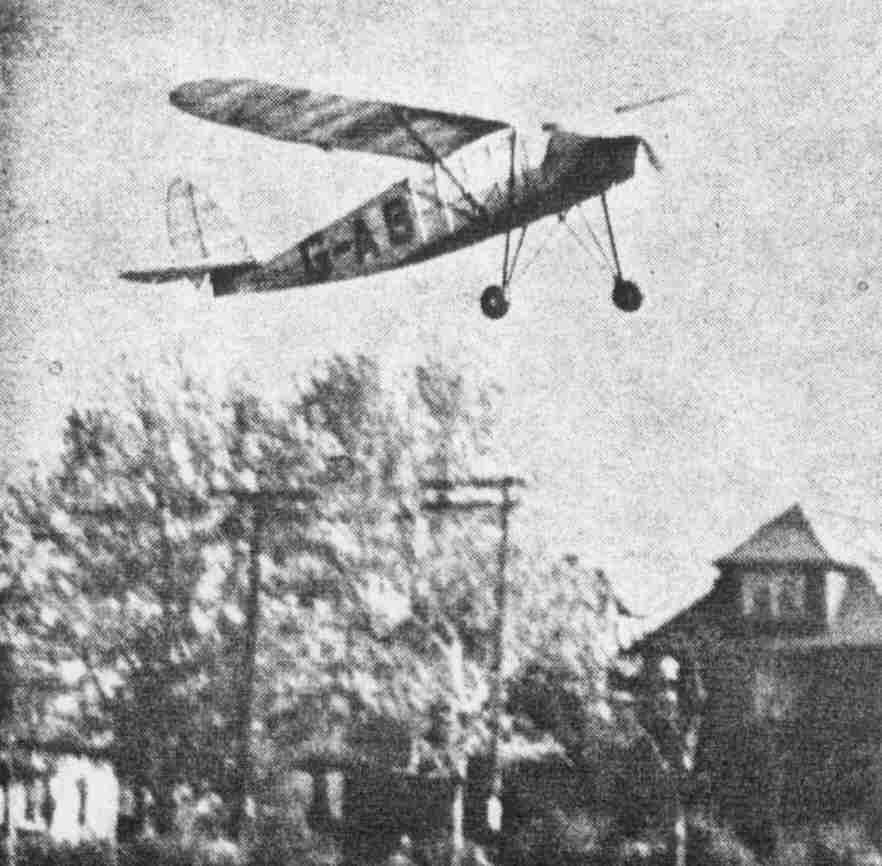
A HIGH PERFORMANCE PUSS MOTH How You Can Build a Scale Model That Will Make By CHESTER LANZO and LEONARD BECKER
THE flying qualities of any model depend more upon good design than upon mere motor power. Stability is the first consideration in selecting an airplane type of which you are to build a model. Therefore when you look over the list of large planes this should be kept in mind and a design selected that you are sure will produce plenty of stability. The Puss Moth is a type which fulfills every requirement in this respect. The fuselage is quite long in proportion to the wing span; the wing is well above the center of gravity, and the general character of the plane lends itself to stability. Therefore the Puss Moth was chosen as an outstanding type for model work. The model itself has been carefully desighed and the measurements have been held very close to the scale and proportion of the original large ship. The choice of this model by Chester Lanzo for entry in the 1938 Scripps-Howard Junior Aviator Contest proved to he a wise one, for he placed third with a flight of one minute, fifty-eight seconds. The model, since that time, has made unofficial flights of over five minutes, nearly going out of sight. It is probably one of the most unusual scale models, from a flying standpoint, that has ever been presented. In fact it is a scale model that gives contest performance. Fuselage Build the two sides of the fuselage right on the drawing, using 1/16" square balsa. Assemble the two sides with 1/16" square balsa cross members, the size of which may be measured from the top view. After the square section of the fuselage is completed, cement the 1/16" square bottom and side stringers in place; the bottom stringers running the length of the fuselage, while the side stringers run from the back of the cabin to the tail. Between uprights "A" and "E," cement 1/16" square balsa uprights to the inner sides of the fuselage, to strengthen the cabin. The motor cowl is carved from a balsa block 13/16" x 1-7/16" x 2-7/16", the sections of which are shown oh Plate No. 3. The nose-plug is made of two pieces of balsa, the size of which is shown on Plate No. 4. The shape of the front piece may be obtained from Plate No. 1, in the top and bottom views. The shape of the back piece may be obtained from Plate No. 4. Wing First cut 1/32" balsa rib to shape from templates on Plate No. 2, then cut the 1/16" square wing spar slots. The leading and trailing edges and bottom spars are then pinned to the plan, after which the ribs and top spars are cemented in place. The wing tips are 1/16" square bamboo, which are formed around a hot tin-can. After the two wing panels are thoroughly dry, they are assembled with two pieces of 1/16" diameter steel wire, being careful to get the right amount of dihedral and sweepback. The edges are then streamlined. Tail Surfaces The outline of the rudder and stabilizer are cut from 1/16" thick sheet balsa and pinned to the plan, after which the 1/16" square cross members are cemented in place. Landing Gear and Tail Surfaces Landing gear struts are made of 1/16" x 1/8" bamboo, the measurements of which may be obtained from Plate No. 1. These should not be cemented to the fuselage until the covering is completed. The size of the wing struts is shown on Plate No. 3. They are cemented only to the wing; (after covering) the other ends having wire hooks. A small rubber band runs from one hook to the other, holding the struts in place, and making it possible to remove the wing. Propeller Carve the propeller from balsa block 1-1/8" x 1-1/2" x 8". A very efficient blade shape is shown on Plate No. 2. Covering and Assembly Tissue cement or nitrate dope is applied with a small brush, and the excess paper is cut off with a razor. After the frames are covered, the wing and fuselage may be sprayed with water. Dope the body with two coats of nitrate dope, but use only one thin coat on the wing and stabilizer, to prevent warpage. Cover windows with celluloid, using nitrate dope for adhesive. Cement landing gear struts to fuselage. Soda straws 1/4" long, which represent exhaust pipes, are cemented to the nose. The stabilizer and rudder are then cemented in place. The motor cover is made of bond paper and cemented on three sides front, top and bottom, leaving back open 3/16". This opening represents an outlet for air, which cools the engine on the real ship. Strips of black paper 1/16" wide are cemented to the window frames, door and motor cover. Paint the fuselage and wings with black dope; the bottom of the fuselage being painted from nose to tail. Letters are made of black tissue or thin black paper and applied with nitrate dope. The wings are held to the fuselage with a loop of 1/8" flat rubber. Flying Power your model with twelve strands of 1/8" flat rubber. Balance the model by holding it at wing tips, at a point one-third back from the leading edge. First glide model, and if it dives, move the wing forward or put a small block under the front of the wing, giving the wing incidence. If it stalls move the wing back, or remove some of the incidence. Then you are ready for powered flights. Scanned From March 1939
|