|
Building a High Efficiency Soarer How You Can Build a Soaring Plane That Will Give a
Performance By PAUL ZAKIM and HENRY CLARK
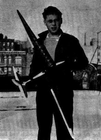
HOW many times have you taken it into consideration to build a soarer as a diversion from your regular routine of building? Have you found it difficult to build one that performs as well as its larger brothers, yet is as simple to construct as any commercial you've yet built? Here is one that is easy to build and is an excellent performer. At present the N.A.A. record for Class "D" tow-line soarers is only two minutes and some odd seconds. The model described here is a serious threat to the present record, and although the model was never officially timed by an N.A.A. timer, it has surpassed the present record many times. Before beginning construction it is advisable that the plans be studied and understood thoroughly. This will allow you to work more smoothly and precisely. Use care in making all your cement joints, and above all, don't rush! Take your time! Any plane that is to be a potential prize winner, must be constructed with the utmost care and accuracy. Fuselage Before beginning the fuselage it is advisable to draw a full size outline of the body, also draw up the cross section full size. Next cut out the cross section templates from either stiff cardboard or metal. Obtain a block of medium hard balsa, 1-1/2 x 3 x 19 inches, making sure that it is straight grained, and free from worm holes and knots. Use the best quality wood you can obtain. Now trace the side view of the body on the block, and with a scroll saw, cut just outside the line. Do not cut out the section in which the wing is to be mounted. This must be cut out last. Next trace the top view and repeat the operation. When this is completed, trim the fuselage outline to the pencil marks by sanding, thereby removing all saw marks. With a very sharp knife, start rounding the fuselage off. Do not try to make the cross section of the fuselage fit the templates as after sanding it will be undersized. Instead, cut it a trifle oversized. Using No. 0 sandpaper, sand the fuselage clean, taking off all knife marks and bumps, constantly checking the contour of the section with each template. Use No. 00 or less to finish off the job. Next give the body three coats of banana oil, sanding lightly between coats. To obtain a high gloss use Johnson's floor wax, following the directions given on the can. Do not be afraid to rub in well. Two coats will suffice. Now, very carefully cut out the grooved section where the wing fits, parallel to the line of flight. Do not try to incorporate any incidence in the groove itself, that will be taken up in the same chapter with the wing instruction. Now cut out weight compartment as illustrated on the plan. When this is finished, cut the slot for the stabilizer. Tail Surfaces Use medium hard balsa throughout the entire tail. The main spar is 1/16 x 3/16 x 16 inches at the root and 1/16 x 1/32 at the tips. The leading edge is 1/8 sq. at the root, tapering to 1/32 sq. at the tips. The trailing edge is 1/16 x 3/16 and at the tip it is 1/32 x 3/16 . Lay out the stabilizer on a flat board, using pins to keep the spars in place. Next cut out the ribs from 1/32 speckled sheet balsa. Notice the inverted camber in the tail, this is very important The tips are 1/32 sheet balsa. Cover the center section with 1/64 sheet as showy on plan. Make sure that everything is dry before sanding preparatory to covering. The rudder is constructed in the same manner as the stabilizer, except tha the rib is a streamline form. Be careful not to allow the rudder or stabilizer to warp out of shape, as this will have disastrous effects upon the flight of the ship. Wing For the wing, make the main spars first. These are to be made from very hard balsa 1/64 x 3/4 inch. Measuring off thirty inches on each strip you will have the full length for one half the wing. This must be tapered to 1/16 sq. The spar of the root section must be cut off at the angle noted on the plan, and also at a point ten inches from the root of the spar another angle is cut, as designated. These angles if cut right, will give the proper dihedral to the wing, for both sections. It is advisable that a full size view of the entire wing be drawn up on tracing paper. The form for the left wing will be obtained by merely turning the paper over to the other side. Wax paper may be used to prevent the frame from sticking to the plan you've drawn. Build the two root sections first using the utmost care in the cement joints and placing of the ribs. The ribs will have to be cut out one at a time, and shaped separately to each one's own size. Each rib after being formed, will be cut in two where the spar passes through them, then they are placed into positions in two halves, front and rear half. The front section of each may be left squared off until the leading edge has been placed and cemented, then rounded off when the wing is completely dried. The framework is then removed from the plan. Bear in mind that each section is to be assembled on the plan, separately from the others. The 1/64 sheet is then applied and cemented to the leading edge, and bent back to meet the top of the spar where it is again cemented, and pinned till dry. The same process is repeated for the bottom of the wing. This type of construction affords a great deal of strength inasmuch as it forms a box spar. At the root rib this covering extends back to the trailing edge as shown and affords a surface for the plastic filler to grip. Take your time on the wing and tail and produce efficiency and not carelessness. Covering and Assembling The covering of the wing and tail surface, is done in the conventional manner and a good grade of superfine tissue is used throughout. Cover the four sections of the wing separately and assemble them later. For good results, lay the frame to be covered, on a piece of tissue slightly larger than its outline, the excess tissue to be used for overlapping. Use banana oil for best adhesive. With a brush, apply a quantity along the leading edge of one of the sections and press the section down tightly onto the tissue. This done, brush the bottom of the ribs and the trailing edge. The bottom of each rib must be brushed as the tissue must stick to it in order to get the maximum efficiency out of the rib section, the lift too being greatly increased. It is not necessary to glue the tissue to the top of the ribs as the tension of the tissue will hold it down tightly enough. So in covering the top of all sections, only the leading and trailing edges may be brushed with the banana oil. Care must be taken in applying the tissue so that no wrinkles are left. The tail surfaces are done in the same manner, cutting just enough tissue for each surface, as too much overlap makes for an unsightly appearance. Before assembling the four wing sections, pin each one down by its four corners to a flat board. Then spray them lightly with a squirt gun. This operation assures a tight surface and eliminates all wrinkles. The pins are used to prevent warp while they dry. The same is done with the bottom surfaces of the wing and tail surfaces. This done, brush on two coats of clear dope. This is done with a very soft brush and spread well. The second coat is applied only when the first is dry. Pin the surfaces down for this operation also, just as a safety measure. Attaching the four sections of the wing together requires a jig of blocks of the corresponding heights indicated on the plan. It is best to cement the two center sections together first, giving them the proper dihedral angle of 3-1/4 in. and resting the ends on the blocks. When these are dry, cement the tip sections on, hold each tip up with a larger block of 5 inches for the tip dihedral. Cement these well, at the same time being careful that neither tip has more incidence than the other. When this is dry your wing is then complete. Do not place the wing in the fuselage groove until you have cemented the stabilizer into its slot. The slot must be at right angles to the vertical axis of the fuselage or the stabilizer will not be level. When it is placed and cemented, the rudder is cemented on the section directly above it and at exact right angles to it. The curve lines on the plan shown leading from the rudder to the fuselage, indicate the location of bamboo strips of 1/64 dia. These strips are built on and curved to position as shown. Then they are covered with tissues and coated well with banana oil. This arrangement provides the greatest streamlining possible for the tail unit. The tail unit will now provide the aligning medium for the wing. Cement two 3/32 flat sheets of about 1/2" x 1" in the wing groove, at the position where the spar will be and meet them in the center of the groove. These will give the proper incidence to the wing. Stand the fuselage on its belly so that the stabilizer is parallel to the table top, and prop in that position. Pile cement into the wing groove. Then carefully place the wing into the groove and press it into the cement. Be careful that the wing is lined up correctly from the top view and see that neither wing tip advances forward more than the other. Dihedral on each tip must be watched also, using the blocks if necessary. The wing will then be properly adjusted. Using plastic wood, fill in the area beneath the wing at the root where it meets the fuselage as indicated on the plan. Continue over the top of the wing with it, as this will provide the maximum strength. This material is best worked in with the fingers if they are dipped in benzine. When this filleting is dry sand to a smooth finish, by using sandpaper wrapped around a 1" dia. bottle. This is then doped for a smooth finish. This filler must not be applied till the wing is perfectly dried onto the fuselage. Flight Instructions Now that the model is completed, it is adjusted for flight by balancing with lead weights or clay. Use a great deal of discretion in picking a day to fly the model. For test flights, a calm day should he sought, with a wind velocity of not more than 8 m.p.h. However, should you wish to make some real time, choose a nice hot summer day with plenty of thermal currents. Test flying requires a bit of skill in order to get results. Glide the model a few times to correct any stalling or diving tendencies. For lateral stability, be sure that it has no tendencies to bank or turn sharply. For an initial tow-line launch, attach a small "S" hook to about fifty feet of silk thread, and in turn attach this to the front hook on the model. Face the model into the breeze and stretch the line until taut. Then when your partner releases it from his grasp, walk forward slowly, breaking into a trot thereby increasing the flying speed causing the model to rise. Look back to observe its progress and action. If it rises steadily run a little faster, then come to a halt, allowing the tow-line to drop and the model to continue on. Should the model drop a wing tip during the climb, change you run to the high-wing side thereby bringing the lower tip up. Never try to attain more speed with a sudden jerk, as this will throw stability out somewhat losing altitude. A little experience in towing, will teach you many tricks in jockeying yoursoarer to high altitudes. The ship presents a graceful appearance when in full flight. Scanned From October 1937
|