|
A Low "Aspect" Indoor Tractor How You Can Build a High Performance Indoor Ship That By CHARLES BELSKY
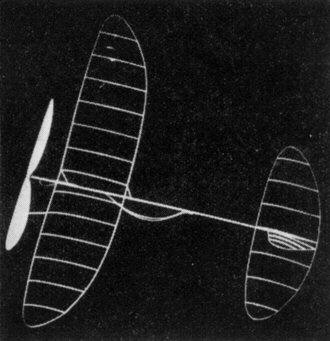
OBSERVATION at most any indoor meet will disclose the fact that the low aspect ratio is rapidly gaining considerable prestige. The author believes that the advantages of the above mentioned type of model distinctly eclipses the so-called disadvantages. Obviously, the foremost advantage is the weight reduction maintaining the necessary structural rigidity. The weight saved overshadows, by far, the loss of efficiency, if any. The drawing is of a plane used by the author at the Mississippi Valley Contest this year. It is a very conservative design reflecting the changing trend. The mentioned model, on an unofficial flight, flew for 19' 40". An unfortunate accident prevented an official flight of more than 16' 11". On this particular official flight the motor contained less than 1800 turns. It has a capacity of approximately 2800. Later this design was equipped with a solid motor stick and with weights and strength increased to take the additional weight of such a motor stick. This model repeatedly flew over 16 minutes. After one particular flight, a time of 16' 13" was recorded. The plane was sent aloft with 1700 turns. Construction Wing: (spars) The spars are of quarter-grained 1/16" sheetwood cut from 5 lb. cu. ft. bulk. Cut 11" long tapering from 3/64" to 1/32" sq. The spars are then cut to 5/64" tapering to 1/32". Sand the spars to an oval section. The four spars should weigh .004 oz. Ribs The ribs are cut from quarter-grained wood. 1/32" sanded to .020" or about 3/128". Use a metal or cardboard template to slice ribs with. The spars are then soaked in warm water for a few minutes and pinned to the plan (full size) and let dry. The soaking of the spars serves two purposes. First, it allows them to hold their shape upon drying. Second, it causes them to expand and assume a larger cross-section adding to the rigidity. The ribs are attached to the spars using as little cement as possible. For correct size hoop for film, use two wire clothes hangers bound together to form one hoop. The wing is then covered as one unit, on this hoop. After covering, the wing is taken off with a hot wire, by trimming around spars. Dihedral is then cracked in and cemented. Loose film can be tightened by heat treating with a hot wire. The clips are then cemented to the wing and your mother's or girl friend's hair can be used to brace the wing, unless the builder himself has long hair. (But, this I doubt from past experience.) The braces are first attached to the spars and then to the clips. Do not tighten braces ; they must be slightly slack else they will warp the wing. Motorsick A quarter-grained blank of 1/64" is sanded to the weight of .009 oz. It is then soaked in fairly hot water for a few minutes. Then bent around a solid former, and either gauze or white tissue or something or other, is wound around to hold shape. Be careful to note whether the seam is straight. Use less than .001 oz. of cement to fasten longitudinal seam. 1/64" sheet is cut 3/4" long. For reinforcement, 2 of these are used in the ends of the stick. The stick is then capped with 1/64" sheet. Finally, the wire parts are cemented on. If the stick is not true then it may be trued by holding over heat, and held to desired shape. Total weight of stick is .011 oz. Use only quarter-grained wood for motor stick and boom. It is more difficult to form, but additional patience will be rewarded by a lighter and stronger stick. Tail Assembly Boom : Motor stick wood is also used for the boom blank. The 10-1/2" blank is sanded to weight .0015 oz. Finished it weighs .0019 oz. Stabilizer and rudder : The stab. construction is similar to that of the wing. The stab. and rudder frame together weigh .0022 oz. Covered they should weigh .0032 oz. Propeller The propeller was carved from average weight wood (5 lb./cu. ft.) Using wood of about 3/ lb./cu. ft. the same prop could be made to weigh approx. .009 oz. Procedure : Select the lightest blocks of wood obtainable, then inspect the radio lines. Use the block in which the lines run at about 45°. This will give your prop full Q.G. about one-half of the diameter. For further details on carving and using proper methods, the author suggests reading the article by Carl Goldberg in the January, 1938, issue of the MODEL AIRPLANE NEWS. Do not depend upon one prop for consistency. Every individual works differently and the weather is so variable that one should carve at least two props of different dimensions. The author suggests these : For average conditions a prop carved from a l3" x 7/8" x l-1/2". For ideal conditions use prop of 13-1/2" diameter of same dimensions as above. If you are using but one prop it is best to vary the motor length accordingly. For example: In normal conditions (usually terrible) use a short motor of about 17" and possibly less. Under good conditions use from 18" to 20" length of motor. Success of your flights depends largely upon your ability to use proper propeller and power. Adjusting and Flying Sighting down the motor stick, see that the right half of the stab. is set at zero degrees and the left half of the stab. is set at negative 3/32". With this arrangement the stab. as a whole has but 3/128" negative or about one fourth of one degree. Consultation of McBride's indoor airfoil chart reveals that in this case the stab. would lose about 5% of its maximum lift. However, because of the added stability during the initial burst, the plane is able to assume its climb without loss of power. After the stab. is properly adjusted, offset the entire stab. to the left about 1/2" (front to rear of the stick), left tip of the stab. is washed down about 1/2". In flight the wing will automatically assume a position nearly parallel to the stab. This also is an aid for power adjustment. Mount the wing on the stick about 1-3/4" from the bearing and give the right half of the wing about 1/4" washin. (This increases the total incidence of the wing to 1/4"). Select proper length motor of brown 1/16" rubber, wet and tie a square knot, use resin or talc on the knot for safety. If the tractor is heavier than required then use a 5/64" motor and place the wing back to 2" from the bearing, to compensate for the additional weight in the rear of the original center of gravity. Glide tractor and if it descends too steeply, check the incidence ; if correct then move wing up 1/4" and if dive still persists add 1/16" incidence and move wing back to the original position. If the tractor at first stalls then check the stab. for excessive negative. If correct, move wing to 2" from bearing. Should the stall continue, remove 1/16" from front clip. If the tractor glides well one may test under power. Wind 800 turns into the motor stretching rubber only twice original length. Launch plane banked slightly to the right and pointed up slightly. If the plane does not assume the proper climb angle, then bend bearing up and retest. If the plane stalls or mushes, bend bearing down. Assuming that the plane acts like a gentleman (not like a woman) under 800 turns, you are now ready to increase turns to 1200. If the plane banks sharply to the left, increase the washin, if it has a tendency to skid or the wing attempts to washout, decrease washin, and increase washout in right wing half. Under full turns the tractor should climb very steeply (30°) in circles of about 20' diameter. With proper adjustments the tractor should descend with less than 150 turns left in the motor. In conclusion bear this in mind, "The more you use your head the less wood you will need." Here's to emery dust in your lub. Scanned From May, 1938
|