|
TOMAHAWK
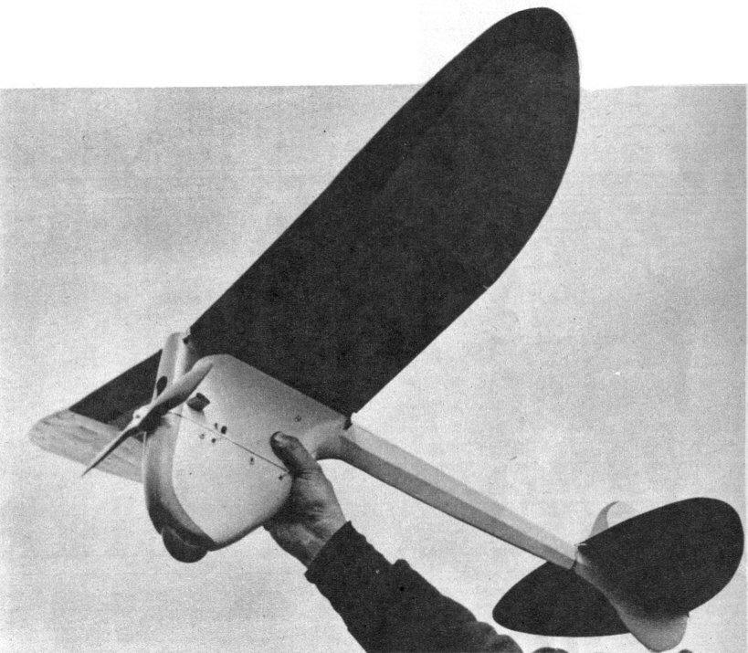
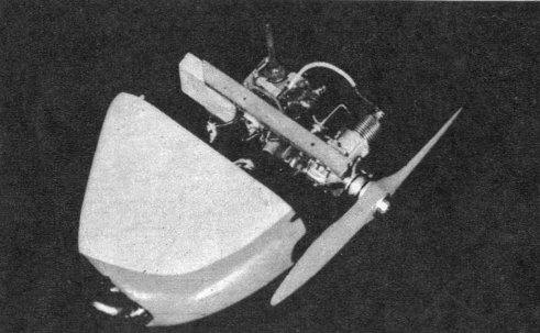
Designed around the new Bantam, this novel job stresses quick engine change at the field for dual competition in both Classes A and B. It is a nice ship to build and fly.
DESIGNED BY MAURICE SCHOENBRUN --- BUILT BY HOWIE BEECHMAN
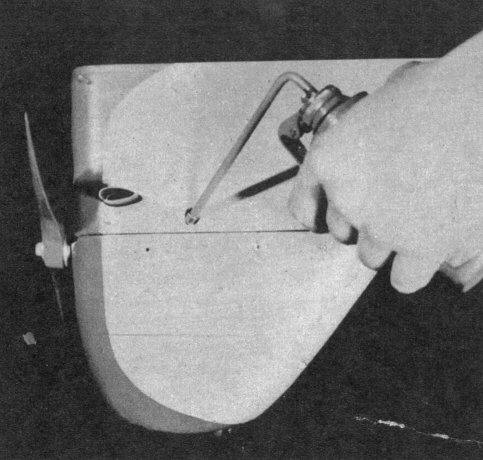
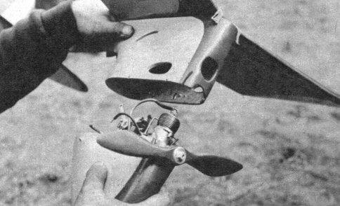
THE Tomahawk, born of a modeler's nightmare, turned out to be a pleasant dream come true. Imagine, if you can, a gas model that may be used for Class A, B, and C, with only a few minutes required to change from one class to another. The Tomahawk has these possibilities, if the motor manufacturers put out a small Class C motor about .31-.35 cubic inches displacement. At present we have two units, a Bantam and an Ohlsson "23," thus making it a two-class job-A and B. As we mentioned before, these units are interchangeable and may be switched by removing four bolts that hold the units in the lower section of the fuselage. Although unorthodox in design, the results obtained more than justified its appearance. Some of the more outstanding features of the Tomahawk (that's some handle, by the way) are: 1. Interchangeable motor units, thus making it eligible for Class A, B, and possibly C. 2. Easily dismantled for quick transportation and storage. 3. Very stable due to its short nose moment, low C.G., and the proper location of the C.L.A. As yet the Tomahawk has not been contest proven, but we hope to go places with it very shortly. Test flights in calm air (no thermals) averaged 1 minute, 45 seconds, to 2 minutes, 30 seconds. CONSTRUCTION The fuselage represents the acme in efficiency and simplicity of construction. The main fuselage (or blade of the Tomahawk) is constructed of 3/16" sheet 5" wide (or one sheet 3/16 x 2" and 3/16 x 3" glued side by side to form 3/16 x 5") and Blocks A, B, C,. and D. All blocks are of soft balsa. Blocks A and B may be cut from 3/4" sheet. Block C is 1-1/2 x 2-1/4 x 5-1/2". Block D is from 1" sheet. All blocks are now tapered as shown in front view. (Dimensions in front view are overall and include the 3/16" sheet sides.) After tapering blocks, glue sides and let dry overnight. When dry, cut assembly to profile as shown in side view. Before rounding and trimming edges, glue upper and lower halves together, lightly. The purpose of this is to have the upper and lower halves conform with one another. After sanding smooth, split the halves apart. Take the lower half and install landing gear as shown. Be sure to cement liberally. The next step is to glue a piece of 1/8 x 1" birch plywood to each side. These act as motor unit bearers. The top of the plywood must be flush with the top of the lower fuselage. Now insert pegs as shown in drawing. The lower half may be set aside and work begun on the upper half. The first step is to build the crutch from hard balsa. See drawing for dimensions. While crutch is drying, glue upper half of fuselage to crutch. Drill a 3/16" hole in upper block to accommodate the lower longeron. The next step is to glue lower longeron into drilled hole and pinch end together and glue, as shown in drawing. We are now ready to insert up-rights and the 1/8" square stringers. See cross section of tail boom. Insert and glue pegs for wing mounts and fuselage clips. Cutouts may be made after motor unit is installed -- this to facilitate the proper location of exhaust hole, etcetera. Now the fuselage is complete and may be set aside. Rudder and subrudder are constructed of 1/4" sheet. Scale up drawings to full size. The outline of the upper rudder is made of soft sheet. Spar and ribs are made of 1/8 x 1/4" medium balsa. While upper rudder is drying, construct lower rudder of 1/4" hard sheet. Glue subrudder to fuselage, then trim edges to form flat airfoil. Upper rudder may now be trimmed and sanded. Stabilizer is constructed in the conventional manner. Lay out leading edge and pin down to plan. Next cut trailing edge from soft sheet. Tips are then notched for the spar which is of 1/8 x 1/2" balsa. Before gluing spar in place, taper it from 1/2" at the second rib from tip, to 1/4" at the tip. Now glue all ribs in place. Ribs are tapered from 1/4" at the trailing edge to 1/2" at the spar. Front ribs are made of 1/8 x 1/2" glued in place and then sanded round to conform with airfoil. Also sand leading and trailing edge to complete airfoil. The wing is nothing sensational but is highly efficient. The first step is to cut all ribs as shown in full-size plate. Next lay trailing edge, which is made from 3/16 x 3/4" soft balsa. The tips are cut from 3/16" sheet. Notch tips for spar, which is made from 3/16 x 1/2" hard balsa. Taper spar from R1 to 3/16 at tip. Next, glue ribs in respective positions. Glue 1/4" square leading edge in place. After drying, trim trailing edge and tip, sanding to a smooth finish. After wing is dry, split at the center and raise tips so that the dihedral at Rib R1 is 1-1/2". Butt-join spar at the center. Place 1/8" sheet on each side of the spar as shown on drawing. Be sure that each side of the wing at Rib RI is 1-1/2". After center joint is dry, cut wing at Rib R1. Spar joint is made in the same manner. Tips are raised to a five-inch dihedral on each side. Next reglue all joints where wing has been broken to form dihedral. Glue sheet of 1/16" along 1/8" square upper spar. When completely dry pull down sheet to leading edge and glue in place. Trim excess. Next step is to glue the 1/16 x 1/4" cap strip, starting from the rear of the 1/16" sheet along the rib and overlapping the trailing edge. This prevents the trailing edge from warping. When all glue joints are dry, sand all edges. Sand cap strips into trailing edge. The wing is now complete and may be set aside. The drawing shows an Ohlsson "23" unit, which we shall describe. Before constructing unit, study drawing carefully. First step is to construct the base or motor mounts which are made from 1/2 x 3/8" gumwood. Next glue into position the 1/2" sheet coil mount as shown in drawing. Drill holes for mount bolt after placing motor mounts in lower fuselage, making sure that mounts are flush with motor bearers. Countersink rear nuts and glue into position; also glue front nuts. This is to facilitate easy removal. Remove unit from lower fuselage. Next construct battery box to accommodate two pen cells. When battery box is completed, glue into position on Motor mounts. Coil may now be placed into mounting and securely glued into position. Timer is mounted as shown in drawing, using a 1/4" strip of .030 brass. This strip is held to the motor mounts with 1/2" wood screws. Next mount condenser by gluing underneath and across motor mounts. Next, motor is installed on its mounts. Take a piece of .040 wire and solder in the form of an x, as shown in drawing; solder this to the top of the needle valve. The purpose of this is to make the needle valve easier to turn from the outside. Next the unit may be wired as shown in drawing. Be sure that all joints are properly soldered. (Remember that a cold iron makes a poor joint.) The timer arm extension is made from a 1/8" bolt. A nut is placed on each side of the timer arm. Solder nut on the left side to the timer arm, making sure that the nut and not the bolt is soldered, as the bolt must be removed before fuselage can be taken apart. Also insert 1/8" peg in Block D which sets into a hole in Block C to prevent shifting of fuselage. Bantam unit is made the same way as the Ohlsson unit except mounts are made from 1/2" square gumwood. Due to the larger size of the Bantam mounts, the sides of the battery box may be eliminated. The tail boom and fuselage are covered with silk. Wet silk so that stretching may be simplified. Wings are covered with light bamboo paper. Stabilizer and rudder are covered separately and glued together after being doped. When doping the fuselage, sand lightly to insure a smooth finish. From three to four coats of clear dope will be sufficient. After model is dry, a few coats of colored dope may be added. The original was painted gray, with red trimmings. Model may now be assembled. Before assembling the two halves of fuselage, make wire clips as shown in drawing. It is best to make about a dozen of these clips as they get lost very easily. Clips are used to hold the two halves together. Wings and tails are held on with rubber bands. FLYING To fly with Ohlsson, wing and tails may be set at zero incidence as the model is balanced approximately sixty per cent behind leading edge of wing. Hand-glide model. If diving tendency is shown, increase positive incidence in wing.. If the model stalls, add positive incidence in stabilizer. When good glide is achieved you are ready for power flight. Give motor slight left thrust and right rudder so it will climb left under power and glide to the right when engine cuts. For Bantam motor use the same procedure as above, with the exception that a small amount of positive incidence may be necessary in the stabilizer as the motor is slightly lighter than the Ohlsson. Now that all has been said and done (we hope) you should go to town. Although the Tomahawk looks like a flying ax, its performance will amaze you. One flight and you will be convinced that you have a potential record holder. Scanned From August, 1940
|
||||