|
THE KINGFISHER Created for those who want a sturdy job for everyday
flying, this ship
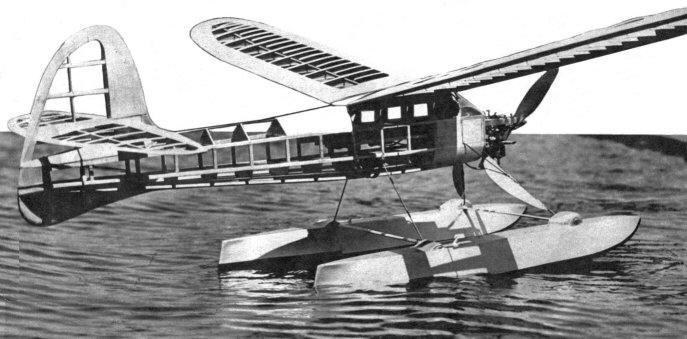
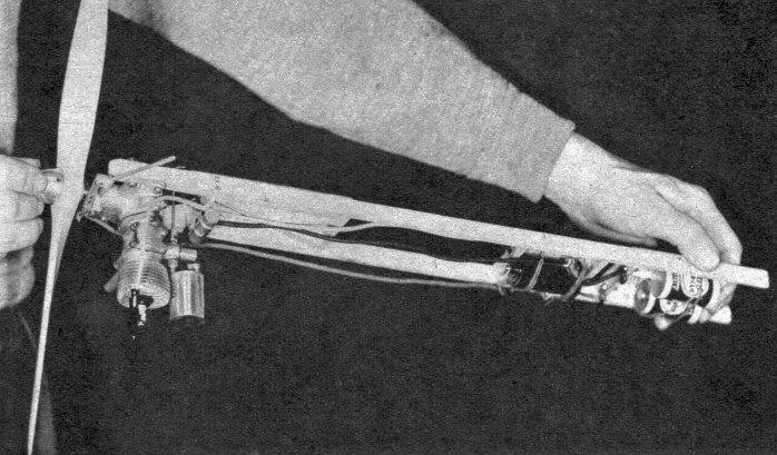
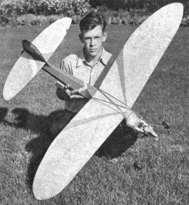
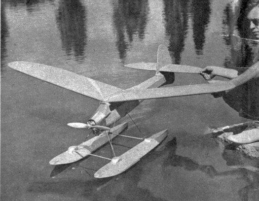
THE Kingfisher is designed to serve a dual purpose -- a land model and a seaplane model. The wing loading averages less than eleven ounces per square foot of area for either plane. The land model has a sixty-inch wing and the seaplane model has a seventy-two-inch spread. The construction throughout is exceptionally sturdy, and hard balsa is used for the most part. Hardwood veneer is used at three main sections of the fuselage. The first one is at Section No. 1, where the landing gear is firmly attached to the body. The second, at Section No. 2, where the leading edge of the wing is held against the top of the cabin, and the third strong point is at Section No. 6, which holds the rear wing hook and strengthens this part against the pressure of the rubber band holding the wing. Four complete test models were built until the final shape and construction methods were decided upon. In the original design the wing loading was to be held at twelve ounces per square foot. This weight would give a little better stability on breezy days and the climbing angle of a heavier model would be more gradual and, in a sense, similar to that of a full-size airplane. The landing gear of a model of this weight must be strong enough to withstand the force of rough landings. By the use of a lifting stabilizer, longitudinal stability is slightly increased, since we have two points of suspension -- the wing and the stabilizer, somewhat similar in a way to a tandem type of airplane. This style of lifting tail, or one along these lines, was employed a few years back on the Handley-Page bomber, and is common on most contest models. Of course, where the tail takes the place of a small wing, the center of pressure of the wing itself must be farther forward than usual, and this should be considered when balancing the model for flying. The position of the center of pressure should be one third back from the leading edge. BODY CONSTRUCTION Material: Longerons, 5/32 X 3/16" sq., hard balsa The body construction begins with the assembly of a rectangular section as illustrated by the heavy lines of the drawing. This method simplifies the starting of a model and permits easy and fast construction. Two identical sides are constructed first of 5/32 x 3/16" balsa. The framework is 2-1/2" deep from Formers 1 to 6. From Former 6 the depth decreases to 1-1/2" at Former 14. Since the top of this framework is perfectly flat, it is easiest to construct the fuselage when in an inverted position on a flat surface. The cross braces should not be cemented in place until all the fuselage formers have been cut to shape. The length of the cross braces is had by deducting 5/16" from the width of the bulkhead. In so doing, the two 5/32" thick longerons will fit flush against the outside of the bulkheads. All material sizes for each part are listed separately. The lower part of the fuselage is built up of formers and longitudinal stringers. Former No. 1, holding the landing gear, is reinforced with 1/8" hard balsa over the veneer former. Note the construction of the rear end of model including the balance box. LANDING GEAR Material: 1 heavy spring wire, .125 dia. x 24" long 1 each medium spring wire, .096 dia. x 24" long 3 each metal straps, 3/8 x 1-1/2 x .020" long 3 sets bolts and nuts, 2-56 x 1/2" brass round head 2 each 3" airwheels The landing gear is bent to the shape illustrated in the perspective sketch, and is bolted firmly through Former No. 1 with metal straps. The reinforcing strut of the landing gear is soldered as illustrated in the side view and firmly anchored to the bottom of the longeron at Section No. 2. The streamlined section of the landing gear should be made from bass or pine, and is not only ornamental, but will actually prevent the main section of the landing gear from unnecessary bending. In addition, it is best to wrap heavy thread in at least two or four places around the landing-gear wire and the streamlined section, applying a generous amount of cement at all times. WING Material: 1 pc. 1/4 x l/4 x 40" long, hard balsa, leading edge The sketches illustrate the construction of the wing, and it should be noticed that the trailing edge is built (box fashion) similar to that of the leading edge. This type of construction guarantees a very rigid an straight leading and trailing edge, which will not warp under the tension of silk and dope The trailing edge should be sanded to a very sharp edge and the leading edge should be sanded to a fairly sharp edge before the balsa sheeting is cemented in place. Cap strip may be left off the ribs; however, an allowance for the space otherwise taken up by them should be made. STABILIZER RUDDER Material: 1 pc. 1/8 x 1/2 x 40", hard balsa, spars 1 pc. (same) 1/8 x 3/8", bard balsa, rear spars 2 pcs. 3/64 x 3 x 24", medium balsa sheet 1 pc. 3/16" sheet, hard balsa, trailing edge 2 pcs. 1/16 x 3/16 x 40" medium balsa, cap strip The leading edges of the rudder and stabilizer are constructed similar to those of the wing. Refer to the perspective sketches illustrating method of assembly. Note in particular that the stabilizer is completed first and that the rudder spars remain in one full piece and are glued against the stabilizer spars. In this way a complete two-unit, rigid assembly is made. The height of the stabilizer can be checked on the side view. FIN Material: 1 pc. 3/16 x 8" hard balsa sheet The fin is a continuation of the rudder and finishes off the lower rear part of the body. It is braced vertically on each side with a thin piece of veneer which prevents breakage from sudden side skidding. A thin piece of wire 1/16" in diameter is cemented to the bottom side of the fin. This prevents wearing away its underside. Motor Mount Material: 3 each 3/16 x 1/2 x 24" pine or bass The motor skid or mount is built as a complete unit which slips into the body and is removable in its entirety with all motor parts held rigidly in position. The timer is mounted just in front of the firewall on the skid and is accessible from the top. The motor illustrated is mounted inverted. The exact position of the batteries and coil is located after the final balancing of the finished model is checked. They are then held in place by hooks cemented to the veneering, and rubber bands passing over the top. Note that the motor skid is anchored in two ways, with a heavy pin running through the top and with hooks and bands on each side. The motor mount slips into two balsa runways, one located on each side of the interior of the fuselage. Propeller Material: 1 pc. 14" dia. pine, 5 or 6" pitch The completed model ready to fly glides at approximately 16 to 18 miles per hour, and it is not advisable to fly much faster than about fifty percent above this speed, which would make the maximum speed between 24 and 27 miles per hour. For instance, if the speed of the motor is 6,000 r.p.m. and the propeller pitch is 6", we should have a normal forward speed of 36,000 inches per minute. This would give us a theoretical speed of 30 miles per hour, and allowing for an approximate slippage of twenty-five percent, we should have an actual speed of about 22-1/2 miles per hour. This actual flying miles per hour figure will vary considerably depending upon the propeller pitch and its slippage and the r.p.m. of the motor. Wire Fittings Material: 1 pc. light wire, .062 dia. x 24" long, wing hooks The wire hooks for the tail unit and motor mount are bent from .047" diameter wire. The wing mounts have the greatest strain and should be bent from .062" diameter wire doubled back to give, extra gluing surface and in addition a 1/8" piece of balsa is cemented and overlaid on the wing hooks. These hooks are attached to the hard wood veneering at Sections No. 2 and No. 6. It is well to keep in mind that they must carry a load of at least 48 ounces under flying conditions and therefore must be attached very securely. The tail fittings run through the body at Stations No. 12 and No. 14 and over the rudder mount, as illustrated in the perspective sketches. Covering Material: Heavy bamboo-landplane For land flying the entire model can be covered with a good grade of heavy bamboo paper. Two coats of clear dope are applied and then the body is painted light blue and the wing light yellow. The photograph of the finished model illustrates the simple decorative color scheme employed. The seaplane model should be covered with silk and doped at least twice and later given two good coats of color. In testing, our seaplane model turned turtle a few times and was pulled out undamaged and unsoaked. The motor also slipped in accidentally with the entire skid -- new batteries were attached, the water pumped out, motor cleaned thoroughly with gas and oil, and in about fifteen minutes was running again. It is impossible to keep a seaplane model dry unless the necessary waterproofing is applied, and for the seaplane model silk must be used. Scanned From February, 1940
|