|
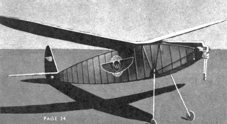
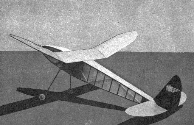
DOUBLE FEATURE Plans for a Class C Sr. Fuselage record holder that flew out of sight and its substitute in 1939 Moffett finals. Longest flight was 22:51. BY GEORGE REICH
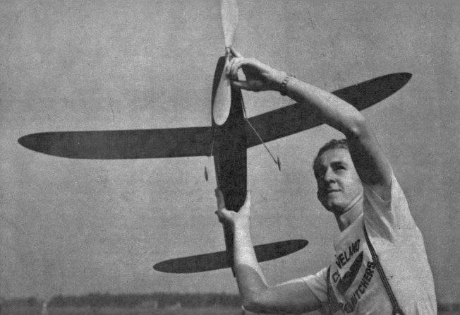
THIS design is the outcome of the Senior Commercial winner of the Scripps-Howard Junior Aviator National Air Races in 1937 and is the ship which I used in the 1939 Moffett Eliminations to set an N.A.A. Class C record of 8:35.5 (three flight average, the longest flight being 22:51). Unfortunately the ship was lost on its record flight and another had to be substituted in the finals. Plans for both ships are included in this article. Those for the record breaker are detailed; those for the somewhat larger ship flown in the finals are in three-view form. This three-view shows the positions of all cross pieces and ribs and is drawn one-eighth full scale. Now let's look at the ship's contest record. At Cleveland, in the eliminations to select representatives to the Detroit Nationals, this design made two out-of-sight flights: 6:35 and 4:02. Then, as mentioned above, the first flight in the Moffett Eliminations was out-of-sight, setting a National record for Class C, Senior Fuselage. The average flight is 3:50 in evening air. There are two original features in the design. One is a new type rubber tensioner that does not slip before catching. The other is an automatic down-thrust adjuster, which decreases the down thrust as power is expended. This is merely a piece of clock spring attached to the lower part of the nose block.
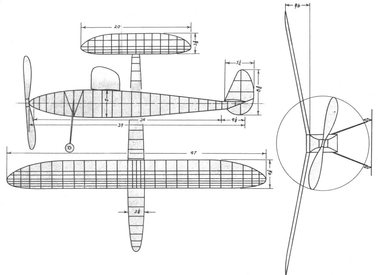
CONSTRUCTION Start first by making full-size drawings of all parts and cover them with waxed paper to prevent work sticking to paper. The body is of rectangular cross section and is built up by first making two identical sides. The longerons of 1/8" square are held in place by pins (not through the wood) and the 3/32" struts are glued in place. The sides may be built on top of each other with a layer of wax paper in between. Let the cement dry thoroughly before taking up the work. The two halves are then joined by building up the rectangular cross section at the widest point first and then working gradually toward the ends. The internal bracing of 3/32" square is then cemented in place. The tail boom is built up with the body and then cut off. The front and rear ends are both filled in with 1/8" sheet balsa, and the metal plate for the bamboo pin is glued in place. The landing gear is of bamboo, 1/16 x 1/4", tapering to 1/16 x 1/8", and is 11" long. It is cemented in place as shown and forms a V, the point of which is at the top of the fuselage. For extra strength, bind with silk thread. The nose plug is made in one piece of hard balsa. Slight down and right thrust are built into the plug. Final adjustments can be made while testing by inserting pieces of hard wood between the nose plug and fuselage. Notes on construction and rubber tensioner are on plans. The automatic down-thrust adjuster is a 1/8" strip of clock spring, 1-3/4" long, curved to a 1-1/4" radius. It is cemented to the lower flange of the nose plug at the center only, being anchored with a U-shaped piece of 1/32" wire. As the tension lessens in the motor the spring pushes the nose block, since the spring is on the lower part of the plug and bears on the two lower corners of the fuselage. As a result the model keeps climbing until the prop stops turning, instead of leveling out and wasting two hundred or more turns. The propeller is carved from a 17 x 1-3/8 x 2" medium block. The blades are not cut for folding until completely finished. Follow layout and blade pattern, as this is important. At the center of the blade 1/8" undercamber is carved in. At this point the blade is 3/16" thick and it tapers to 1/8" at the tips. Give a high polish with four coats of clear dope. After prop is balanced it is cut as indicated in the drawing. It is necessary to cut on the given angle in order to have the blades fold flatly for least resistance. Hinges are then glued in place and wrapped with silk as shown on the plans. The prop shaft is 1/16" music wire. The plans give the details. In making the wing, start by pinning the leading edge, 1/8 x 5/32", and trailing edge, 3/32 x 5/16", in place. Cut the tips from 3/32" sheet and glue in place. Using the rib template given, cut nineteen ribs and cement in position. Finally, the 1/16" square top spars are installed. When dry, cut the wing at the dihedral breaks and raise the tips 3-3/4" for the required dihedral, and recement, using 1/16" hard sheet balsa reinforcements as detailed on the drawings. Finish by putting in the 1/16" square bottom spars. Ribs are medium-grade wood ; spars, hard. The stabilizer is constructed in a similar manner to the wing. The thirteen ribs are cut from medium 1/32" balsa, as are the 1/8" square leading edge, 1/16 x 1/4" trailing edge and the 1/16" flat tips. The 1/16" square spars are hard balsa. The rudder has a flat cross section and is made entirely from 3/32 x 3/16" medium-hard balsa. In calm weather the model can be flown very nicely on eighteen strands of 3 /16" flat, 32" long. In breezy weather add two extra strands. The model is covered with regular Japanese tissue. The wings are red, the tail and fuselage dark blue. Probably, this color scheme is one of the reasons why the model remained in sight for 22:51. Do not try to cover too much area at a time. Water-spray after covering has dried on framework and apply two coats of clear dope. In assembling, the stabilizer is glued on the tail boom, with the bottom of the stabilizer resting flat on the top of the boom. The rudder is glued on top of the stabilizer with 1/16" offset to give a right circle. The wing is given 3/16" incidence and is attached to the fuselage with two strands of 1/8" flat rubber. The rubber motor is held at the rear by a bamboo peg 3/16 x 3/32 x 2-1/4". The entire tail is held in place with rubber hands hooked around the bamboo pin. See the drawing. FLYING Test the model in the evening when there is little or no wind. Wind motor about a hundred turns and let unwind to bring tensioner into operation. Before every flight, make sure that Part D of tensioner is in position (Figure 1). Next adjust the wing until a smooth glide is obtained when hand-launched. Give motor about two hundred turns and launch into the wind. It should turn to the right and spiral upward. Adjust for turn by giving it more, or less, right thrust. Correct stall with down thrust until the model climbs almost straight up on these few turns. Don't be afraid about looping, because the automatic clown-thrust adjuster will take care of the power under full power. When the model climbs to the right without stalling on two hundred turns and has a flat soaring glide, then the fun begins. Remember to use a good grade brown rubber and never let it become dried out or it will break easily. Scanned From June, 1940
|