|
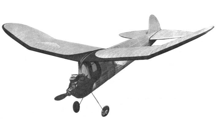
BROOKLYN DODGER Nationals winner Taibi produces another tried-and-true
warrior.
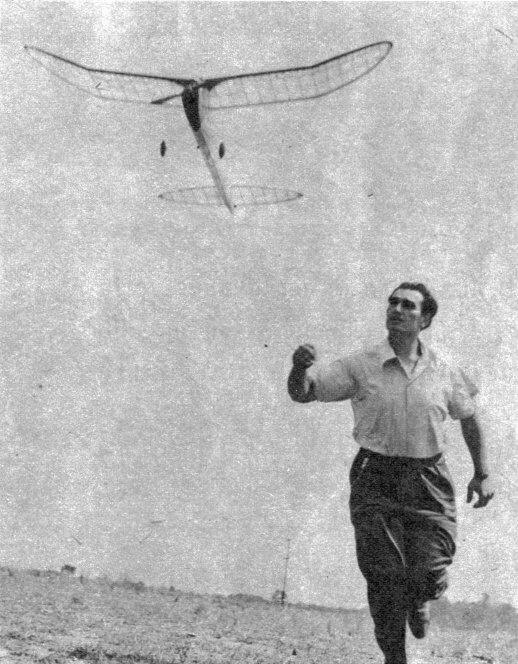
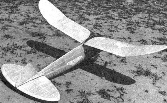
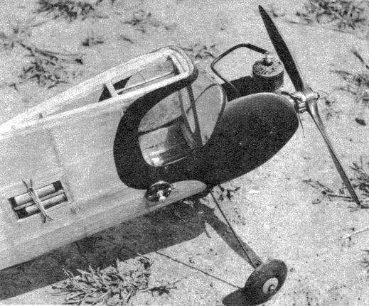
THE Brooklyn Dodger is a super-simple gas model to build, and one that has very good flight characteristics. The climb will amaze you; it climbs at about forty-five degrees and is extremely fast under power. On the test flights the ship was consistently turning in flights of 3 minutes on a 16-second motor run, so clean off the bench, fellows, and put everything where it is easily accessible so you won't waste any time and get started on one of the best flying ships I've ever owned. CONSTRUCTION The fuselage is of crutch construction, which the author has found to be one of the strongest types of fuselages that can be built. First splice a gumwood motor-mount bearer into the crutch, then lay the crutch down on the board and insert the cross braces in their proper positions. Bulkhead A is cut from 3/32" plywood and the other bulkheads are cut from 1/8" sheet balsa. The bottom halves of the first five bulkheads (A, B, C, D and E) are identical, and a good way to save a lot of grief when assembling the ship is to pin these bulkheads together and cut the 3/32 x 1/4" notches all at once. This will assure perfect alignment later on. The notches for the crutch, of course, are cut individually. Remove the crutch from the board and insert bulkheads. After these are in place, a strip of 14"-square soft stock is glued from the top of Bulkhead D to Bulkhead H. Individual pieces of 3/16 x 1/2" are glued between the bulkheads to give greater strength. The bulkheads are mounted on the crutch by first sliding them into their respective spaces until one notch engages the crutch, and then twisting into place carefully so that the bulkhead rests flat against the cross piece. The lower rear former that connects the bottom stringer and crutch is glued in place. The 3/32 x 1/4" bottom stringers are glued in place. The cabin wing rest is cut from 1/4" sheet balsa and cemented to tops of Bulk, heads A, B, C, D. The 1/4"-square, top longeron is cemented in place, as are the 3/32 x 1/4" side stringers. The landing gear is cemented in place with a piece of 3/8 x 1/2" grooved basswood; glue at least four times! If in doubt, consult sketch on plans. The cowl blocks are next glued in place and shaped. It will be noted that although the motor is fairly well cowled, the needle and other parts of the motor are easily accessible. The engine is wired according to plans. Motor mounts are bolted in place with 1/16" bolts. The stringers right behind the firewall are filled in with 1/8" sheet. This is to prevent the firewall from backing up on a hard landing. The window is covered with celluloid. It is advisable to cement the body again before covering. Next, the fuselage is covered, either with silk, bamboo paper or Silkspan. Since the fuselage is subject to spray of gas and oil from the engine exhaust, the fuselage should be given at least six coats of clear dope. The dowel pin to hold the wing in place is 1/8" diameter. It is inserted into Bulkheads A and B. The rear dowel is braced in a triangular piece of balsa just in front of Bulkhead D. The tail skid is embedded into the balsa keel at the rear of the fuselage. It is 1/16" diameter piano wire, and also serves as a hook for the tail. In its test flights the ship was found to need a little more incidence, so two wedges were glued to the wing rest connecting the first four bulkheads. These wedges are 9-1/2" long and measure 3/16" at the thick end. In designing the Brooklyn Dodger, simplicity of construction in the wing was one factor that was given particular attention, such as simple sparring, butt leading edges, et cetera. In constructing the wing it will be necessary to elevate the front wing spar 1/16" above the board. Pin the lower front spar to the board, slip all the ribs in place, attach the trailing edge and then the leading edge, glue the top spar in place. The rear spar is cemented in place after the wing has been removed from the board. Repeat this procedure to build the other half of the wing. The false ribs are inserted between the full-size ribs. The wing is then joined at the proper dihedral angles as shown on the plans. Finally, cover with either bamboo paper or Silkspan. The rudder is built flat and is selfexplanatory. After the rudder is built, the tab is attached to it with strips of aluminum. The stabilizer is flat in construction. The leading edge is cut out of 1/2" sheet, the trailing edge from 1/4" sheet. After the edges are cut out, lay down the spar, then leading edge and trailing edge. The ribs of 1/8 x 1/2" are glued in place. When dry, remove from the board and cut the ribs to airfoil shape. (See stabilizer detail.) FLYING The Brooklyn Dodger has been thoroughly test-flown and therefore all the incidences are built in. There is no side thrust, but there is two degrees downthrust. First glide the ship until a smooth glide is obtained. It may need minor adjustments such as 1/16" incidence under either the leading or trailing edge. The first flight should be at half power, with about a 20-second motor run. Study the flight characteristics carefully, and if the ship performs satisfactorily, fly it again with slightly more power. Repeat this procedure until a fast, zippy climb is obtained. The ship will climb in a very wide left circle and glide in a tight left circle. If any information is needed, write to Sal Taibi, c/o Air Trails, 79 Seventh Ave., New York City. Good luck! BILL OF MATERIALS
Scanned From January 1942
|
||||||||||||||||||||||||||||||||||||||||||||||||||||||||||||||||||||||||||||||||||||||||||||||