|
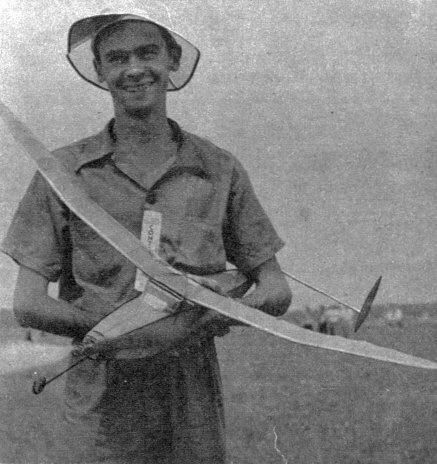
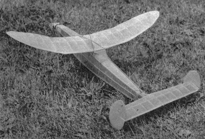
THE VETERAN It's a consistent winner. Placed second in the
HIGH performance and simple construction make the Veteran a constant threat. The original ship placed first in the Middle Tennessee Meet in 1938. Jack Schneider took first place in the Allegheny County Meet flying a similar ship and then Dick Everett, who later won the Class C Open Gas at the Nationals, and Schneider placed first and second respectively in the West Virginia State Championship Meet. Flown by the author, this design piled up a 503.73 - second three-flight average to take second in the Open Class Moffett Eliminations at the 1939 Nationals. Longest flights were 27 minutes unofficial and 18 minutes official out-of-sight. Now for interesting features in design. The original ship, built by Dick Everett, used a single rudder. The twin rudders were used to increase the stabilizer efficiency. Directional control was also better after the twin rudders were introduced, and torque was reduced, the ship needing very little offthrust. The stabilizer was raised to its present position to escape the downwash of the wing. The stringers down the sides of the fuselage add greatly to the strength, with a minimum of weight. Although the ship had a slightly better glide with the folding prop, I used the freewheeling because flying adjustments were easier to make. In contest flying, to me, this is important. The folding propeller, which changes the center of gravity when the blades fold back, makes adjustment more difficult between the power and glide flights. The rubber tensioner is important, and well worth the time of making, since it allows the use of tip to twelve inches of rubber slack. CONSTRUCTION Lay the plan on a flat surface and place thin wax paper over the side-view layout of the fuselage. After cutting two each of the upright stations, pin the longerons in place. Cement the stations in place. Make two sides just alike. You may make both sides at once, if you choose, by laying longerons and stations on top of each other, as you cement them in place. Cut top and bottom stations. Join the two sides together, starting with the widest station and working toward each end. Check frequently to see that the fuselage is square and in alignment. Box in nose and tail as shown with 1/16" sheet balsa. Add side and bottom stringers. Cut the backbone piece and formers from 1/8" sheet, and fit in place on top and between the cabin and the rear of the fuselage. Make a pattern of the stabilizer mount and cut two from 1/4" sheet. Glue together and sand to a streamline shape. Cement solidly to the rear of the fuselage. Fillets inserted at Stations A and D are sanded to shape as shown in cross section. Bend 1/16" landing gear wire to pattern shape, and bind well with thread at each corner. Cement well. Add tail skid. Now, with a sharp razor blade, cut the rear of the fuselage in two. Prepare the rear hook hangar by bending the rear hook around a 1/4" square basswood piece, and cementing well. Cut the basswood hangar to fit tightly into the shell and cement into position. Now, cut 1/8 x 1/2" pieces to fit the four inner sides of the tail piece. Leave about 1/4" extended so it will fit snugly into the fuselage proper. This allows tail assembly to be removed for winding. The wing and stabilizer are built in the usual manner. Laying the spars directly over the plan, proceed to cement the ribs in place. Add the leading and trailing edges and form the tips on the wing. Sand to shape as shown in cross-sectional view. After wing is completed, put in dihedral. The gussets will give approximately the correct angle, but check. Careful work in carving the propeller will repay you many times by long flights. The back of the blades are first cut to a flat surface. Next, cut the rear face of the blade so that it has an undercamber of about 1/8" depth. Cut the blades to shape, sanding down and balancing. Apply three or four coats of dope, sanding lightly after each coat. The blades should taper to about 1/8" thickness at tips. Drill hole in center for prop shaft, and cement washers on both sides. Make the hook for freewheeling and cement to prop as shown in sketch. Now, make the nose block, cementing 1/4" pieces together crossgrained. Thrust hangar is made by cementing large-faced washers on both sides after the hole through the center has been drilled. Place wire "stop" for rubber tensioner in the nose block. The best way to do this is by drilling holes in large-faced washers and soldering wire in; however, bending a hook on one end and cementing it in the block will do very well. Leave "stop" longer than shown in plans so it may be cut down for adjustment. Make tensioner spring by wrapping wire (.020) around a 1/8" diameter nail or screw, leaving about 1/16" space between each loop, the entire spring about 3/4" long. Bend prop shaft from 1/16" diameter wire, starting at the rubber hook. Be sure to make rubber tensioner arm long enough to engage "stop." Now add the nose block, a ballbearing washer, a large-faced bushing and prop -- in that order. The spring is soldered to the ballbearing washer and to the large-faced bushing. The bushing is soldered to the shaft itself. The bending of the freewheeling hook completes the propeller assembly. Cover the model in the usual manner, running grain of paper parallel to the line of flight. The fuselage is covered with red tissue, the wings and tail with yellow. Shrink covering with water spray. When dry, apply coat of clear dope. TESTING AND ADJUSTING Select a very calm day for testing model. Make several trial glides. If your model shows stalling tendencies during these glides, move wing back a bit. If it -- dives, move wing forward. Do not move too far in either direction -- rather, change the angle of incidence. This may be done by placing a small piece of balsa under the leading or trailing edge, as the case may be. After the glide is satisfactory, wind the model about one hundred turns, increasing the number of turns gradually on each flight. Adjust carefully each time the number of turns is increased. Correct stalling in the climb by negative thrust. This is done by inserting thin pieces of balsa between the top of the nose block and the first fuselage cross brace. The model should circle to the right, both under power and in the glide. The rudder tab will control the circle in the glide. Probably one degree right thrust will be necessary to get right thrust when under power. This may be obtained by placing a sliver of balsa between the nose block and the first station of the fuselage on the left side. Fly the Veteran in your contests.
Scanned From August, 1940
|
||||||||||||||||||||||||||||||||||||||||||||||||||||||||||||||||||||