|
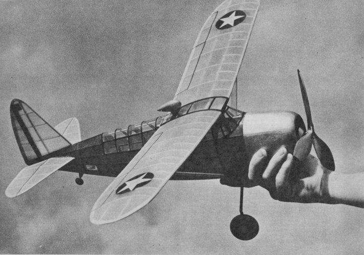
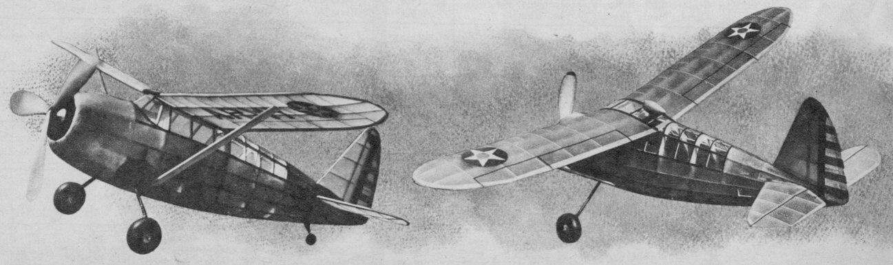
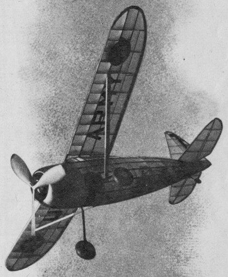
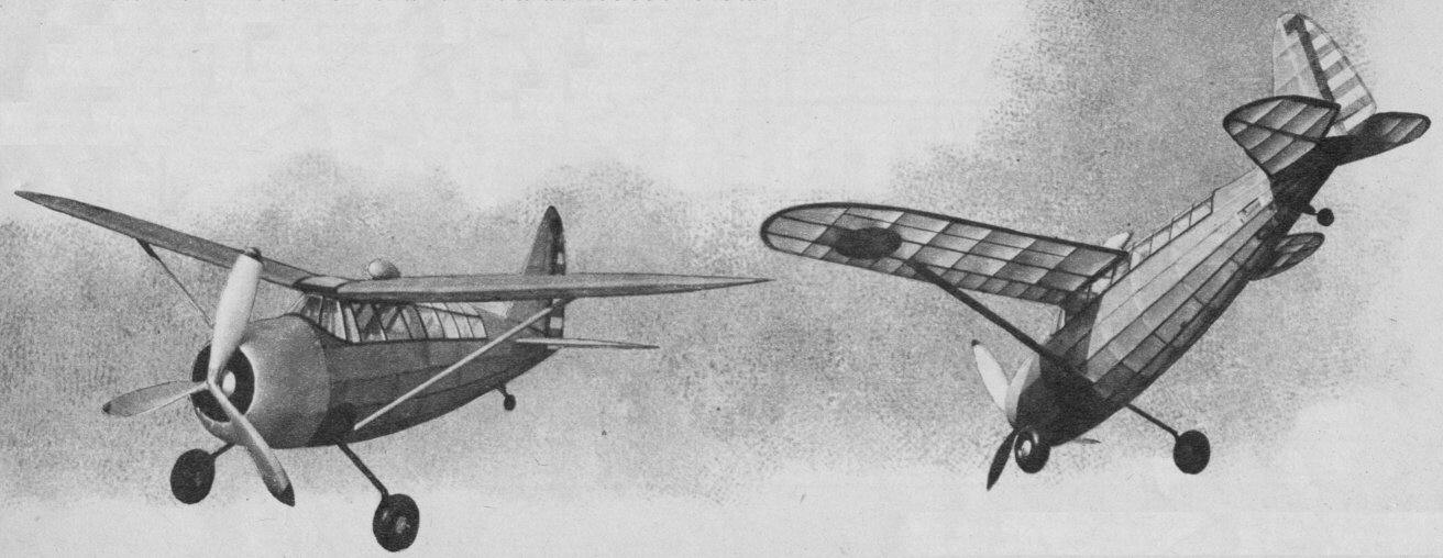
SCALE THE CURTISS 0-52 BY RONNIE ALBERT Realism and high performance are combined to an amazing
ONE of the latest and most talked-about U. S. army war birds is the new Curtiss Observation -- the 0-52. Designed especially for "peeking" duty, the 0-52 is one of the most efficient in its class. And although few realize it, aircraft of the observation type are just as important, if not more so, than those 400-m.p.h. fighters! This 0-52 will make as beautiful and consistent a flying model as the real ship is efficient -- and that's something! Having a wing area of 129 square inches and a total flying weight of 4 ounces, our 0-52 is just up to weight rule -- a characteristic of extreme importance in flying-scale competitions. The construction is rather simple and no difficulty should be encountered if the directions are carefully and accurately carried out. As with most flying scale models, the fuselage is by far the most difficult unit to construct -- so, before that enthusiasm is lost and you start to cool, let's get on with the construction.
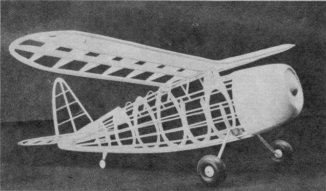
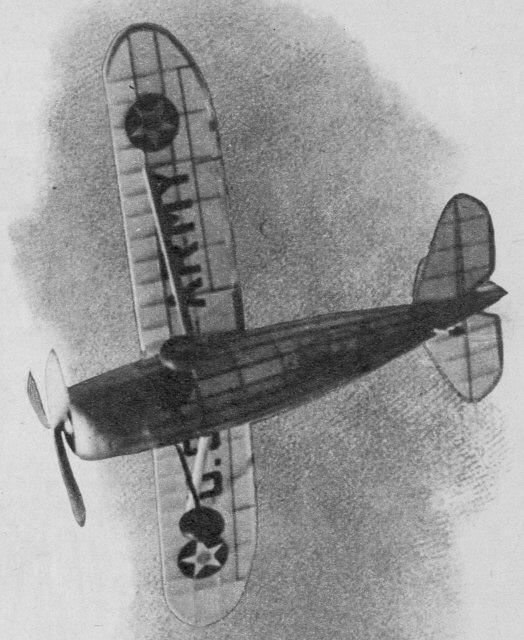
CONSTRUCTION With the assumption that you have already enlarged the plans to read full size or else eliminated "model builder's torture" by sending your thin dime to Air Trails for the full-size drawings, start the construction by cutting out the bulkhead halves from 1/16" stiff medium sheet balsa. After the bulkhead halves are carefully sandpapered and labeled, cut from 3/32" medium sheet balsa the fuselage "keel" and pin directly over the drawings. Then cement each bulkhead half in place, care being taken to make certain that all are perpendicular to the plan surface. After the cement has sufficiently dried to permit handling without the fear of bending the bulkheads from their perpendicular position, the 3/32" square "line-up" stringer should be cemented in place. You will note that when cementing stringers in place, all are cut down from Bulkhead B to C to make way for the 1/16" sheet nose balsa covering which is later cemented into place. After a check-up to make certain the line-up stringer did not pull the bulkheads out of position, the fuselage half may be removed from the plan and the other bulkhead halves cemented into position. The right-side line-up stringer should then be added and the entire structure allowed to dry. After the cement is dry, cement the 3/32" square stringers in position, adding one to one side and then one to the other to insure a true fuselage. Next we plank the nose with flexible 1/16" sheet balsa. You will note that because the stringers were shaved between Bulkheads B and C, the sheet covering is flush with the stringers -- all of which makes way for a smooth covering job. After the planking is completed the solid nose section should be made. First cut two "rings" from soft 1/2" sheet balsa. Cut out the center of each ring so a 1/4" wall remains, and then cement both rings in place. Next add the front 3/8" thick solid section of sheet balsa, and proceed to carve the nose until it fits in with the fuselage contour. Cut 1/8" into the front layer to give the effect of a cowl, and drill a 3/8" diameter hole for the hardwood nose block. Apply a few coats of clear dope to the balsa surface to fill the pores, and then proceed with the cementing of the landing gear in place. The landing gear is bent from .035 steel wire to the shape indicated, and cemented in place to the face of Bulkhead C1-C1. Cut the 3/16" diameter fairing struts from flexible balsa and cement in place. To obtain a neat job, it is best to groove the fairing to fit the wire and then cover the entire strut with tissue paper. Next cement the rear hook and tail wheel in place; add the cockpit braces along with the wing rest bulkhead, and then sandpaper the entire structure with No. 0 sandpaper to make certain no nicks and bumps result. In making the stabilizer, first cut from 1/16" medium sheet balsa the ribs, and cement in place along the 1/8" square spar. Add the leading and trailing edges, and then sandpaper the structure with No. 1/2 sandpaper. Because each stabilizer half is symmetrical it is not necessary to make one right and one left, and consequently the stabilizer is made in two identical halves and then joined individually to the fuselage. The construction of the rudder is our next task and, since this is very similar to the stabilizer construction, little need be said. A word of warning, however. When making the rudder, be certain that the ribs bevel to fit the trailing edge, else small wrinkles will result at the point where the rib and trailing edge meet. Now that we have the framework of our tail surfaces completed, our next job is making the wing. Because of the fact that the wing is of the nontapered type, wing construction is very simple. Cut the ribs from stiff 1/16" sheet balsa and cement in place along the spars. Both front and rear spar are cut from a sheet of 3/32" stiff sheet; the front or main spar measures 7/l6 x 3/32", while the rear spar is 3/8" deep. Add the 1/8 x 3/8" trailing edge and then cement the 1/4 x 1/8" leading edge in place. Trim off both leading and trailing edges to work in with the contour of the airfoil and then sandpaper the joints carefully. You will note that the wing is made in two sections -- one left and one right. 1-5/8" dihedral in each tip is cemented in place when the wing panels are joined together. Reinforce the joint by cementing 1/16" sheet to the rear of each spar at the point where they join at the center. Although many of the current flying-scale models use the conventional two-bladed propeller, we are inclined to believe that the three-blader is a bit more effective, and consequently equipped our O-52 with such an airscrew. (Anyway, the real ship has a three-blader.) A three-bladed propeller may seem rather difficult to build up, but actually it isn't. In fact, it will be much simpler to make than a two-bladed prop of equal diameter. You will note that the drawings contain two prop block outlines. For those of you who worry about appearance a bit more than flying ability, we suggest you use the outline as indicated by the dotted line. As for you other modelers, you know what to do, so we won't bother putting it on paper. First obtain three individual blocks -- all equal in size and weight -- and then cut the outline with a coping saw. After the outline is completed, proceed with the actual carving on one blade, starting with the underside. After the underside is completed to the degree where about 3/32" undercamber exists, the upper side should be carefully carved. Each blade tapers from about 3/16" at the extreme hub to 1/16" at the tip. Round off the tips so they are of an elliptical outline and then bevel the hub so when all three blades are joined together 120° exist between the center lines of each blade. Use the same process in making the remaining two blades, and then, after all three are carefully sandpapered and matched, join together. To reinforce the propeller hub, a section of 1/16" plywood is cemented to the front of the prop. A 1/8" hard balsa hub reinforcement is anchored securely to the rear. As an extra reinforcement measure, three .035 wire braces bent to the shape shown on the plan are cemented between the propeller hubs. The propeller is then fitted for freewheeling and doped three times with thick clear dope. After this is done, cover the entire surface with tissue paper and paint silver. The prop shaft should be bent from .048 steel wire and the loop covered with rubber tubing to prevent the rubber motor from being cut. As for power, power your model with eight to twelve strands of 1/8" flat brown rubber having about 4"- 6" slack. COVERING AND ASSEMBLY Before covering the fuselage with blue Silkspan tissue, the cockpit should be covered with a light-grade celluloid; that is, celluloid that bends easily. Do not cover the portion near the wing trailing edge with celluloid until after the wing is attached to the fuselage. After the celluloid is in place, the fuselage may be covered and then sprayed with a light coat of water. When the covering is dry and taut, dope the surface a few times with thin clear dope. Next cover the stabilizer and rudder with yellow paper -- the covering material in all cases being Silkspan tissue -- and cement the stab and rudder accurately in place. The wing is next covered with yellow tissue and given the same water and dope treatment as the fuselage and tail surfaces. The wing is cemented in place and, after the cement is dry, the 1/8 x 1/2" streamlined wing struts are added. The celluloid center section is then carefully installed and the direction loop finder, which is carved from soft balsa, cemented where shown. To bring out that American touch, the Stars and Stripes are added to both wing and rudder, respectively, and the 2"-high U. S. army letters cemented to the underside of the wing. The aileron elevator hinges and flaps are indicated by strips of 1/16" wide black tissue, applied with fairly thin dope. To give the appearance of the space where the retracted wheel fits in, the portion indicated on the plan is painted black, as is the landing-gear strut and the entire nose plate. FLYING Knowing model builders, we realize these flying directions will only be glanced at -- because everyone has his pet way of testing a job. At any rate, for your model's sake choose a nice calm day for that "first," with the surrounding area consisting of high grass -- the higher the better. Balance your O-52 at a point between both wing spars and glide the model to notice the turning tendencies. Warp the rudder so the gliding tendency is toward the left, and put a sliver of bamboo in the nose block to slant the thrust line to the right. Thus your model will climb to the right and glide to the left. And when that winder is put into play the climb will be right and the glide -- gee, that'll be right too! Scanned From December 1941
|