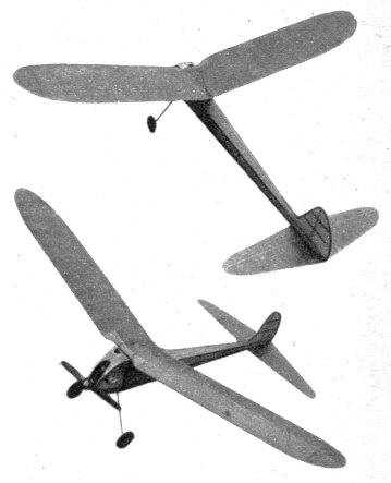
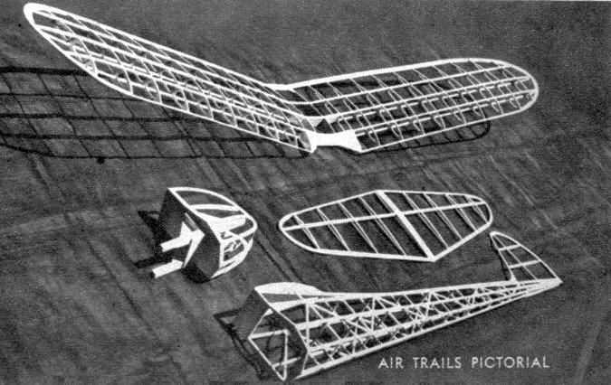
HERE y'are, boys -- a gas job, complete, ready to fly, without even a splinter of balsa in it. Here are some of the advantages: First, it's cheaper, as you can always pickup some scrap pine or spruce and have a friend strip it for you. Second, the all-hardwood construction makes possible a tough and resilient framework that can "take it" better than any balsa model. The design lends itself to contest work very well -- what with its thin flying surfaces, general sliminess, high-lift airfoil, generous moment aria, and reflex section stabilizer airfoil. If you have a Rogers 29 or similar motor on hand, try building this unusual ship. The original model gave the authors quite a shock in that it didn't quite reach weight rule, necessitating additional doping and heavier batteries. The most outstanding characteristic, however, is the flexibility of the model. Subjected to plenty of flying and transportation manhandling, the model is still in perfect condition. Impacts have shattered the tissue at times, but the framework is still as sound as the day it was assembled. You, too, can make the Pinch Hitter. It's easy. First, two main side frames are constructed of 1/8" square pine, spruce, or what have you. Even mahogany is 0.K., but don't saw the legs off the family piano! Almost any type of glue can be used, as parts of the original model were held together with Weldwood,. Casco, and regular cement. No difference in strength has been noticed, but it should be mentioned that three coats of cement were used where formerly one sufficed. Allow the main frames to dry by working on some other part to take up your time. The cross pieces are now cut out according to the lengths given in the top view. The two sides should be assembled directly over the top view before adding stringers. See sketch on plan for details of braces that run through fuselage to support the stringers. Odd lengths can be used here, as they will be trimmed to exact size before the stringers are added. These braces should be fastened to the cross braces and uprights with a few turns of thread and at least two coats of cement to secure them in place. Since the rudder is so simple, it may be assembled right on the fuselage once the curved sheet pieces have been cut out and the outline cemented together. All that remains is to fit the spar in place and bend the cap-strip ribs around it. Do not forget to taper the last inch of the spar tip so that it blends into the thin curved-sheet outline above it. Wing-mount formers W-1 are now cemented in place, care being exercised that they remain flat while the cement dries, providing a smooth area for the wing to rest on. The stabilizer is constructed next. Pin down the outlines directly on the plan and place the bottom rib cap strips in their respective positions. The spar is tapered now and fitted in place, followed by bending the top rib cap strips over it to obtain the desired camber. Cut the bottom portion of the rudder to outline shape and cement to the cambered side of the stabilizer. The wing ribs are cut out of 1/16" sheet pine en masse, once a motordriven jig saw has been located. Maybe one of your friends has a vibrator-type saw, which will be highly satisfactory. Cut eighteen sheets of wood to the necessary width and length, and after they have been lightly nailed together, trace the main rib outline on the top one. Now you can go to town with the saw, but be careful, as an airfoil with smoothly blended curves is the only type that is efficient. Cut the trailing edge short on two of these ribs to obtain the # 11 ribs. The tip ribs (#I2) are now cut out, followed by cutting out the centersection ribs (three required) which are split vertically to allow space for the spar joiners. Assemble both panels on a flat surface and allow to dry well. After propping up the tips 6-1/4", the spar joiners may be added (see sketch on plan). After the cement or glue has dried, cover the center-section leading edge with two-ply bristol board or similar material to strengthen the center portion that has a "cut out." Use colored silkspan for covering all the framework now assembled. Spray all covered areas with water and allow to dry. Pin wing and stabilizer down so that warping will be minimized while the tissue is drying. Three coats of clear dope should give the model a slick appearance and help protect it against spilled oil and gas. A wide stabilizer platform may be cemented to the bottom of the fuselage to steady the stabilizer, but it is not absolutely necessary. The motor mount is now assembled. The sketch of the assembled mount should clear up any questions. The full-size pattern for the nose bulkhead appears on the plan. After inserting the 3/8" square motor runners in the nose bulkhead, gussets should be added to reinforce them. Fill in the bottom rear of the motor runners to obtain a platform on which the battery box is fastened later. The landing gear is bent to shape directly over the plan and should check with the full-size pattern before it is fastened in place. Drill small holes in the bulkhead and "sew" the landing gear on with fine copper wire. Cement or glue should be applied liberally now to give the nose and landing gear plenty of strength. After slipping the wheels in place, solder retaining washers on. Follow the diagram given on the plan when assembling the ignition system. Use a hot iron and don't skimp on the quality of solder or flux, lest you let yourself in for a mess of trouble later. Although designed for the most compact unit possible, the ignition arrangement may be deviated from if desired. Only remember that moving the heavy parts, such as coil or batteries, will shift the c.g., spoiling the flying set-up. The cowling is made by assembling a light framework of formers on the plan and covering with two-ply bristol board. After covering with silkspan, cut cooling hole and make a paper exhaust stack to direct the exhaust away from the fuselage. If an Austin timer has been used, a hole should be cut in the top of the cowl for access to the timer handle. It should be noted that the timer on the original model was trimmed on one side to allow it to be cemented nearly flush with the nose bulkhead. Scanned From November 1942
|