|
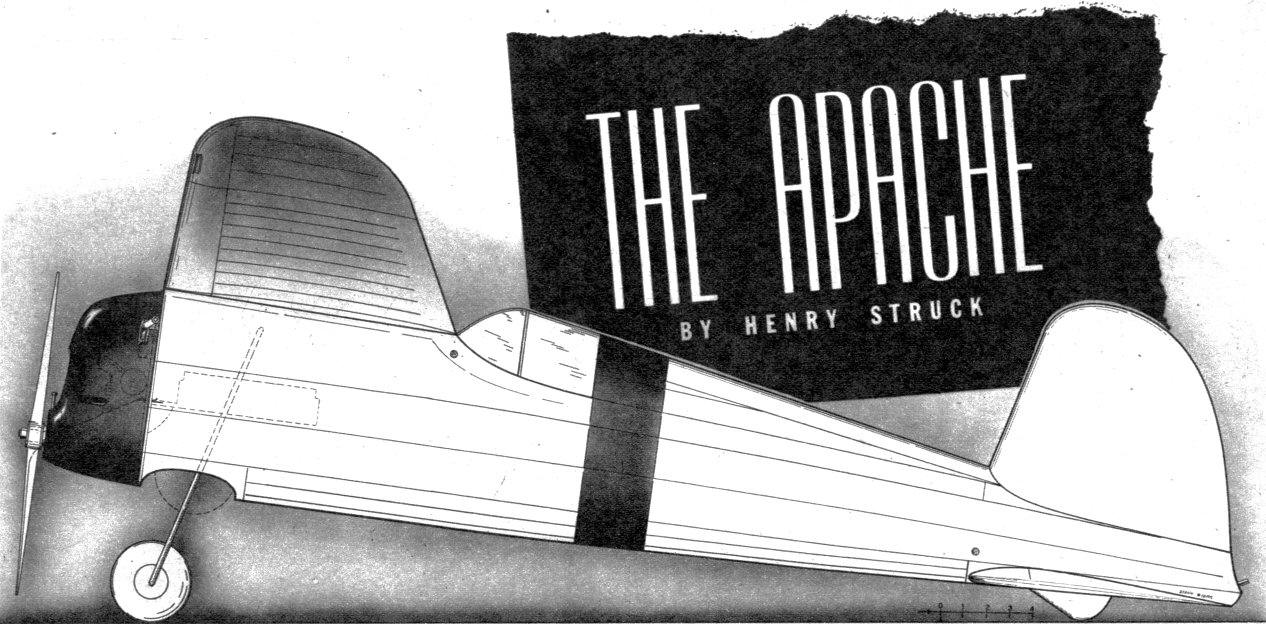
Foolproof retractable landing gear, wing slots to kill stall, and automatic and adjustable sailplane "spoilers" to prevent undesired out-of-sight flights make this trim warrior your best contest bet. Power is by Super Cyclone. The first of two parts.
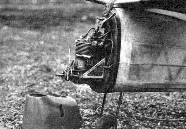
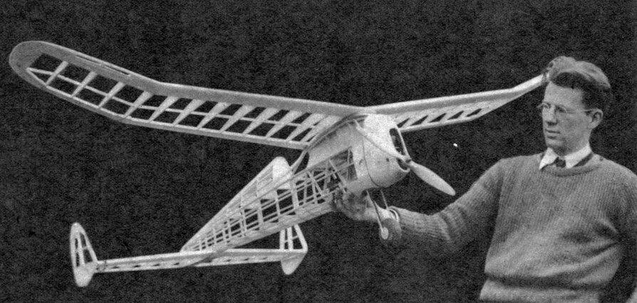
EVERY possible device for obtaining maximum stability and efficiency has been incorporated in the Apache, without sacrificing the realistic appearance most modelers desire. Stability is achieved by the proven set-up of high wing, large stabilizer, and proper rudder design, plus built-in tip slots. These delay the stall of the tips when the wing reaches a high angle of attack, overcoming the tendency to fall off on one wing and start a spiral dive. The stabilizer is set low out of the turbulent wake of the wing airflow, affording greater stabilizing action at high angles of attack. Efficiency is attained by "cleanlining" the ship without using fancy construction. In order to make a retractable landing gear practical, a singlewheel design was necessary. The system used is positive in action and can be locked in extended position for test flying. The inclosed cockpit has been carefully worked into the fuselage lines to reduce its effect to the minimum. Construction is practical throughout, with no difficult wood bending required. The motor unit is designed for instant checking and shock-absorbing qualities. Should the propeller or engine strike an obstacle, the motor bulkhead will swing out, with the pivoted battery track following without raising havoc inside the fuselage. To facilitate transportation, the wing and stabilizer are removable, and are keyed to assure replacement in their proper positions when ready for flight. Powered with an Ohlsson 60 or a Brown, the required weight under A.M.A contest rules is 3 pounds, giving the ship a wing loading of 8.2 ounces per square foot, while with the Super Cyclone the minimum weight is 3 pounds, 4 ounces, raising the wing loading to 8.8 ounces per square foot. Any of these engines will pull the Apache high into the sky where its slow, flat, soaring glide will take advantage of every foot of altitude gained under power. FUSELAGE CONSTRUCTION The fuselage is built up around an inner frame of l/4" square balsa to simplify alignment. Lay out the side view in full size using the fuselage dimension chart given on Plate I. Note that the dimensions are given from the outside of each longeron to the center line. Assemble both sides at the same time, one atop the other to assure their being exactly alike. Join the sides from Stations 1 to 7. Pull the longerons together at the rear-and install the stern block of 1/2" sheet. Fit the required cross pieces to complete the structure. Now decide whether you wish to install the retractable landing gear, or prefer the conventional two-wheel type -- which is best attached later directly to the motor bulkhead. . The operation of the retractable gear is fully explained on the plans. Cut out the two main plates F-2 of 1/8" plywood. Make the bearing fittings consisting of 3/16" O.D. tubes with .040 brass strap (F-3) soldered to them. Be sure that the inside diameter of the tubes is slightly more than 1/8" to allow the struts to slide freely. Bolt these fittings to the plates using filler blocks to get the proper width for the struts. These fillers may have to be slightly more or less than 3/8" thick, depending on the accuracy with which the struts are bent. Bend the landing gear struts of 1/8" wire. The best way is to bend the lower part first without the wheel. Straighten out and slip the wheel in place. Now when bending the wire back, it will tend to bend in the same place as before. Slide the struts through the fittings and bend over the tops. Leave the wire long and cut off after bending to give spurs about 1/2" long. Cement the unit solidly in the fuselage. Form the trigger of 1/16" sheet aluminum and pivot it on a 1/16" wire shaft, inserting a large face bushing in the plate as a bearing. Push a stop bar under the trigger to prevent the gear from jamming when extended. Form the rubber hooks of .049 wire and set in positions shown. Adjust the tension of the bands so that the thin bands will just barely raise the trigger against the pull of the larger, or retracting, bands. Trace the formers and bulkheads from the full-size patterns given on Plate III onto the stock specified. Lay the 1/8" sheet wing mount floor and cement the top formers in position. Insert the turtleback stringers of 1/16 x 1/4" balsa and fill in between T-l, 2, 3 and 4 with 1/16" sheet to form a box structure. Cut the wing rest roof of 1/4" sheet and cement it in place, cutting a small hole in the top to permit access to the trigger rubbers. Attach the cockpit formers F-5, the side stringers and the 1/16 x 1/8" beading strips that prevent the covering from sticking to the inner frame. Cement the nose bulkhead of 1/8" plywood in place and add the bottom formers. Insert the bottom stringers of 1/8 x 1/4" balsa and cover the wheel well with 1/8" sheet, moistening it slightly to facilitate bending. Cut the headrest blanks from 1/4" sheet and glue them together. Shape this block to the proper cross section with knife and sand-paper and cement it to the turtle-back. Form the motor unit hooks of 1/16" wire and anchor them solidly in place with numerous coats of cement. Smooth the entire framework with successively finer grades of sandpaper to remove any bumps that may spoil the finished appearance. Form the rudder outline of 1/4" aluminum tubing. If tubing of the thick wall variety is obtained it will prove easy to form with the fingers; otherwise it may be necessary to fill the tube with fine sand to prevent buckling. Cement the rudder outline in place. Install 1/8" hardwood dowels to serve as rubber hooks for mounting the wing and tail. Cement four large face bushings in which short lengths of l/16" wire are inserted, to the top of the wing rest and the bottom of , the tail rest to serve as keys. The fuselage is now ready for covering. Silk is excellent both for strength and ease of application. The fabric can best be applied in four sections, sides, bottom and top. Wet the silk thoroughly and spread it in place. The wet material will stick to the frame and make it a simple matter to work out the wrinkles. Then apply a heavy coat of dope around the edges and pull out any small wrinkles before the dope dries. Brush on two more coats of dope when the fabric is dry because the dope does not stick well to wet wood. To cover the wing rest, cut a piece of ample size and lay it in place, spreading it roughly into position. Apply dope to the center area, pulling it taut vertically, using pins to hold it in place if necessary. Then draw in the front end, pulling lengthwise, and dope the rear to the cockpit former and join to the turtleback covering. . When the wood and fabric are dry, apply several more coats of dope to prevent the silk from springing loose, and re-move the pins. Do not permit the silk to stick to any of the formers or the contour of the fillet will be spoiled. Apply three or four coats of clear dope, polishing between each with 10.0 sandpaper to remove the "fuzz." MOTOR UNIT CONSTRUCTION Trace the motor mount bulkheads M-l and M-2 from Plate III onto the plywood specified. Cement and brad the keys of 1/4 x 3/8" pine to them. Trace the full-size motor mount blank onto 1/16" sheet aluminum. Cut out the blanks with a hacksaw, clamp them together and file to exact shape. Bend them to shape over the rounded corner of a hardwood block by tapping them with a mallet. Be sure to make one right and one left. Drill all the holes except the motor bolt holes. Form the battery track pivot from .049 wire and clamp it in place between the top pair of bolts. Wrap a piece of .040 brass around it and bolt to the battery- track of 1/8 x 1" pine. Bend the spring of .034 wire and clamp it to the bottom pair of bolts, bracing its upper end against a short 1/8" dowel peg. Construct the battery box of hard 1/8" sheet with 1/4" ends. Form a pair of battery springs and cement in each end. Bolt the timer and the coil to M-l. Cut holes into the fuselage nose bulk-head F-l where these bolts project in order that the motor unit will lay flush against the front. Slip the motor unit into the fuselage and lash it in place with a 3/32 x 3" rubber band wound between each pair of motor unit hooks. Drill one hole and set the engine in place, and adjust the thrust line until it is not offset in any way. Then drill the rest of the holes. Remove the motor unit and install the wiring. The system given will operate on boosters alone when the timer is switched off. Mark the plus and minus leads to avoid crossing the batteries if boosters are used. Apply a couple coats of shellac to the motor unit and the front bulkhead to protect them from the ravages of gas and oil. If a two-wheel landing gear is desired, it may be attached by three small clamps bolted in place with the motor mounts as shown on Plate II. Next month the construction of the wings and tail will be covered, and the Apache will be ready to go on the warpath.
Scanned From June 1941
|
|||||||||||||||||||||||||||||||||||||||||||||||||||||||||||||||||||||||||||||||||||||||||||||