|
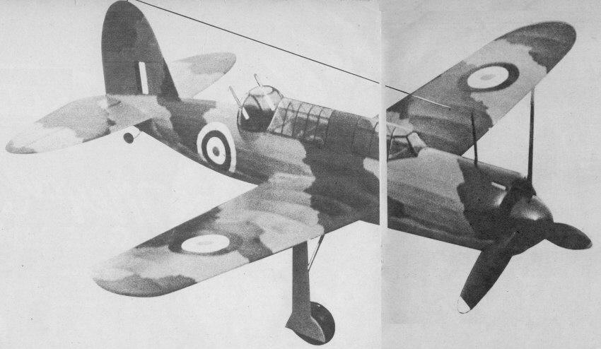
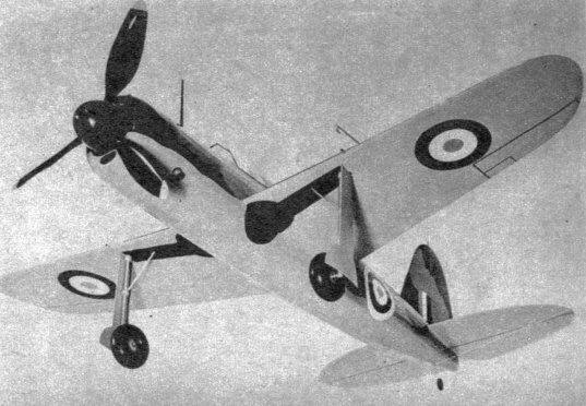
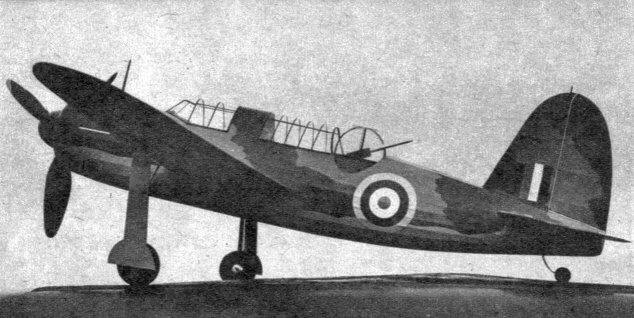
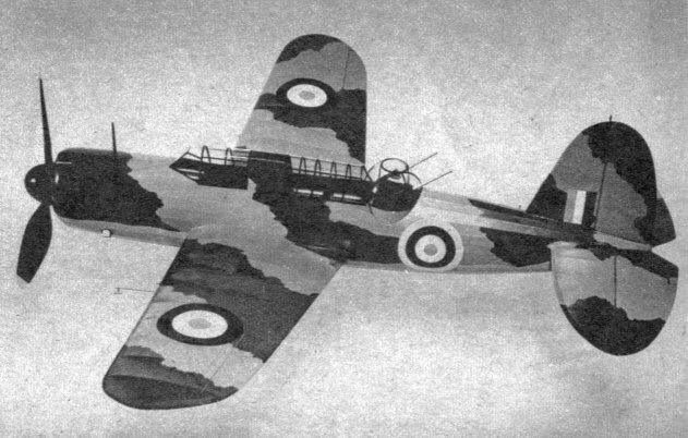
As natty as any detailed solid-scale model, this Bermuda flies with all the dash of its deadly big brother. Note the power, turret. Fly This Bermuda Dive Bomber BY CHARLES H0LLINGER A super job any way you look at it, size, looks, performance. From power turret to its carefully copied camouflage, this 4-footer is tops among flying-scale models.
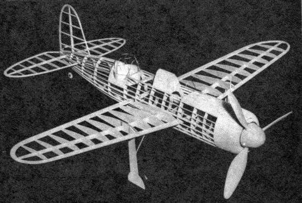
TO the British it's the Brewster "Bermuda." In our navy it's the "Buccaneer" (SB2A-1). Either way, the plane is one of the deadliest dive bombers of this war. Carrying either two 500-pound bombs or one 1,000-pound bomb within the fuselage makes it much cleaner in design than the famed Stuka. The crew consists of two, the pilot and gunner. Incidentally, the power-operated turret is the first to be used on an American two-seater. Our model Bermuda has proven itself not only to be an exceptionally realistic and accurate scale model, but a very steady and capable flier as well. The fine flying ability can be attributed in part to the large wing span of 47". After flying the Brewster with rubber power, why not try installing an Elf Single or Super Atom? The model is strong enough to take a small gas engine. CONSTRUCTION Start by tracing the fuselage bulkheads onto the 3/32" sheet balsa. Cut these out carefully and notch for the stringers and "keels." With the bulkheads completed, trace the exact shapes of the bottom, top and side keels on the 1/8" sheet balsa. The top keel extends from Former No. 1 to No. 4. The rear top keel from No. 10 through No. 13 to the tail block. The bottom keel extends the full length of the body. Pin the bottom and top keels directly over the plan and cement all the bulkhead halves in place, being careful to keep them perpendicular. As soon as these are rigid enough, lay one of the side keels in place along the center notches and cement. While this is drying, cut the pieces for the front of the cowling from 1/4" sheets. Remember to remove the centers from the first three front laminations. Cement the cowl pieces together and allow to dry. Carefully remove the fuselage half from the plan and cement the remaining bulkheads in place on this first half. Next cement the side keel in place, being sure to see that the formers are kept in correct alignment. The 1/16 x 3/16" stringers may be put on now. In attaching the stringers, work on both sides at the same time so as not to pull the fuselage out of line. If, while attaching the stringers, it is found that some notches are out of line, enlarge these so that the stringers are not wavy. The cowl may be cemented in place now. Pick out a sheet of 1/16" soft sheet balsa that will bend easily and cover the top of the fuselage from. the cowl to Former No. 5. The photos of the framework will show how much to cover this way. Cut two pieces 1/16 x 1/4 x 11". These are cemented along the sides of the fuselage from No. 5 to No. 9, forming an attachment for the celluloid cockpit inclosure to be put on later. With the sheet covering on, proceed to carve and sandpaper the laminated cowling to shape, again using the photos as a guide.. The wing construction is simple and yet strong. It is constructed in two parts. Two of each type ribs are required; ribs are cut from soft 3/32" sheet; that is, all except the two No. 4 ribs. These should be cut from hard 3/32" sheet, since the landing gear must be attached to them. The wing spars are tapered, so cut from 3/16" sheet 24" long. They taper from 11/16" to 5/16" at the tips. Lay the wing spars on plan and cement ribs in place. It is best to taper the leading and trailing edges before cementing to the ribs. Notch trailing edge for ribs, as this makes for a sturdier and warp-free wing. The wing tips are built up of 3/16" and 1/4" sheet. Trim the wing tips to shape and sandpaper smooth. Bevel the spars, leading and trailing edges for correct dihedral. It will be necessary to remove a part of the first stringers below the side line-up keels just ahead of Former 5 in order for the leading edge to go through the body. Insert the wing panels into the fuselage and raise the tips 4-7/8" if you measure from the bottom of the fuselage, but remember the wings have 3-1/2" of dihedral when measured from the bottom of the center of the wings. After the correct dihedral has been put in and the fuselage checked to see that it is sitting correctly, cement the wing halves together inside the body and cement the wing where it touches the fuselage also. Don't be stingy with the glue here. Cement gussets made of hard 1/8" balsa on both sides of the spars where they join at the center. Tail surfaces are simply built, using a strip 1/8 x 1/2" for the stabilizer and rudder spars. The stab spar is tapered from 1/2" at the center to 1/4" at the tips. Trace and cut the leading edge from 1/4" sheet and 3/16" for the trailing edges. Cement the outlines together around the spar, then cut the 1/16" sheet into half-inch-wide strips and cement in place for the ribs, being sure to double cement where they join the spar. The rudder is constructed the same way. After the tail surfaces are thoroughly dried, shape the tops of the ribs to a streamline form, then remove and repeat on the bottom. With the tail surfaces finished, it will be O.K. to cement them onto the fuselage. The stabilizer is set at a negative angle of two degrees. The rudder is not offset. The landing gear is formed from 1/16" wire, although 5/64" wire may be substituted, giving a sturdier gear. The wire is cemented to No. 4 rib, with a hard piece of 1/8" sheet grooved and cemented to the same side. A triangular piece of 1/4" balsa is cemented next to the 1/8" sheet. This sandwiches the wire in, giving a strong attachment. A piece of 3/32" aluminum tubing is wrapped with a strip of silk or paper, which is cemented securely to the two No. 3 ribs. The landing-gear strut itself, is sanded round from a piece of 3/8" square hard balsa. This is grooved and cemented to the landing-gear wire only, and not to the wing rib, so leave a space between it and the rib so as to allow for flexibility. The original model used 2-5/8" M & M airwheels slightly overinflated. Don't despair when the spinner is mentioned, for all you have to do is obtain a soft block 3 x 3 x 3". The next step is to "beg, borrow or steal" an electric motor and drill a hole 1/2" deep the diameter of the shaft. Run grain of block with shaft. Cement spinner block to motor shaft and allow to dry overnight at least. The prop blades are carved from hard balsa. Sandpaper each blade and give them four coats of black dope, sanding lightly between coats. The tips are trimmed with yellow. If the spinner block is now securely cemented to the motor, locate a jackknife or any sharp-pointed instrument; turn on the motor and begin now to roughly. shape the block, using a template of the spinner as a guide. Do the final shaping with sandpaper. Give spinner three coats of clear dope and three coats of camouflage green, sanding lightly between coats. This finishes the spinner, so it may be cut off. It will now be necessary to drill holes in the spinner for the attachment of the prop blades. Drill holes 1/4" deep. Extra strength will be had if a length of 3/16" aluminum tubing is inserted in the prop blades, leaving half of the tubing extended which will be cemented into the spinner when the prop blades are put in place. The prop shaft may be cemented onto the 1/2" round dowel or piece of hardwood. A 1/2"-diameter hole will have to be drilled into the spinner now to take the hardwood piece. Be careful to get this centered correctly so there will not be any wobble to the spinner. Now's the time to put in the rubber. Make up a motor of thirty strands of 1/8" flat rubber. No slack was used on the original. White rubber model Silkspan is recommended as it is possible to use it wet for covering the difficult spots. Start with the fuselage, using either clear dope or banana liquid as the adhesive. In covering the body do not use too-large pieces as this causes wrinkles in the covering. Cover the balsa-covered parts of the fuselage and cowl also. When covering the wings be sure to run the grain of the paper spanwise to the wing. The tail surfaces are easily covered; again run the grain of the paper the same on top and bottom. After the complete structure is covered, spray lightly with water and set aside to dry. Give model one coat of clear dope as soon as the paper has dried. With all the modern warplanes being camouflaged with "sand and spinach," it would only be proper to do likewise on our model. It is not possible to purchase the exact colors, so it will be necessary to mix them. Darken the green by adding a small quantity of black at a time until the desired shade is acquired. The brownish-sand color is made by adding black to orange, making a light brown. Some yellow is added to bring out the sand effect. Brush two to three coats of sand color on first to approximately the right outlines. When applying the green make the edges irregular. The underside is doped a light blue-gray, which is made by mixing a little blue into the white; a very small quantity of black is added, too. Be sure to paint on the dummy wheel wells and the inside of the cowling black. The proper outline shape of the celluloid inclosure is found by the cut-and-try method, using paper as the template which is traced onto the celluloid. Use a ruling pen and drawing ink to put the black outlines and detail on the celluloid before applying to the model. Before taking the model out of the workshop, check to see that it balances when held a quarter inch behind the wing spar. Add weight to the nose or tail until it balances horizontally at this point. Now check wing, stabilizer and rudder to see that no warps are present. If some part is even slightly warped, hold that part over a small electric hot plate and carefully bend to proper angle; take away and hold until surface has cooled. This system works swell on gas jobs, too, but for Heaven's sake don't get it too hot! FLYING If a large smooth field is available, start the test flights by the ROG method. Start with just a, few turns at first, gradually increasing the number until it hops off for its maiden voyage. A small amount of right thrust may be necessary to make the model circle to the right under power. If on the other hand your field has tall grass, it will be necessary to hand-launch the Brewster. Start with about fifty turns, gradually increasing the number twenty five each flight. Many happy landings!
Scanned From April 1942
|
||||||||||||||||||||||||||||||||||||||||||||||||||||||||||||||||