|
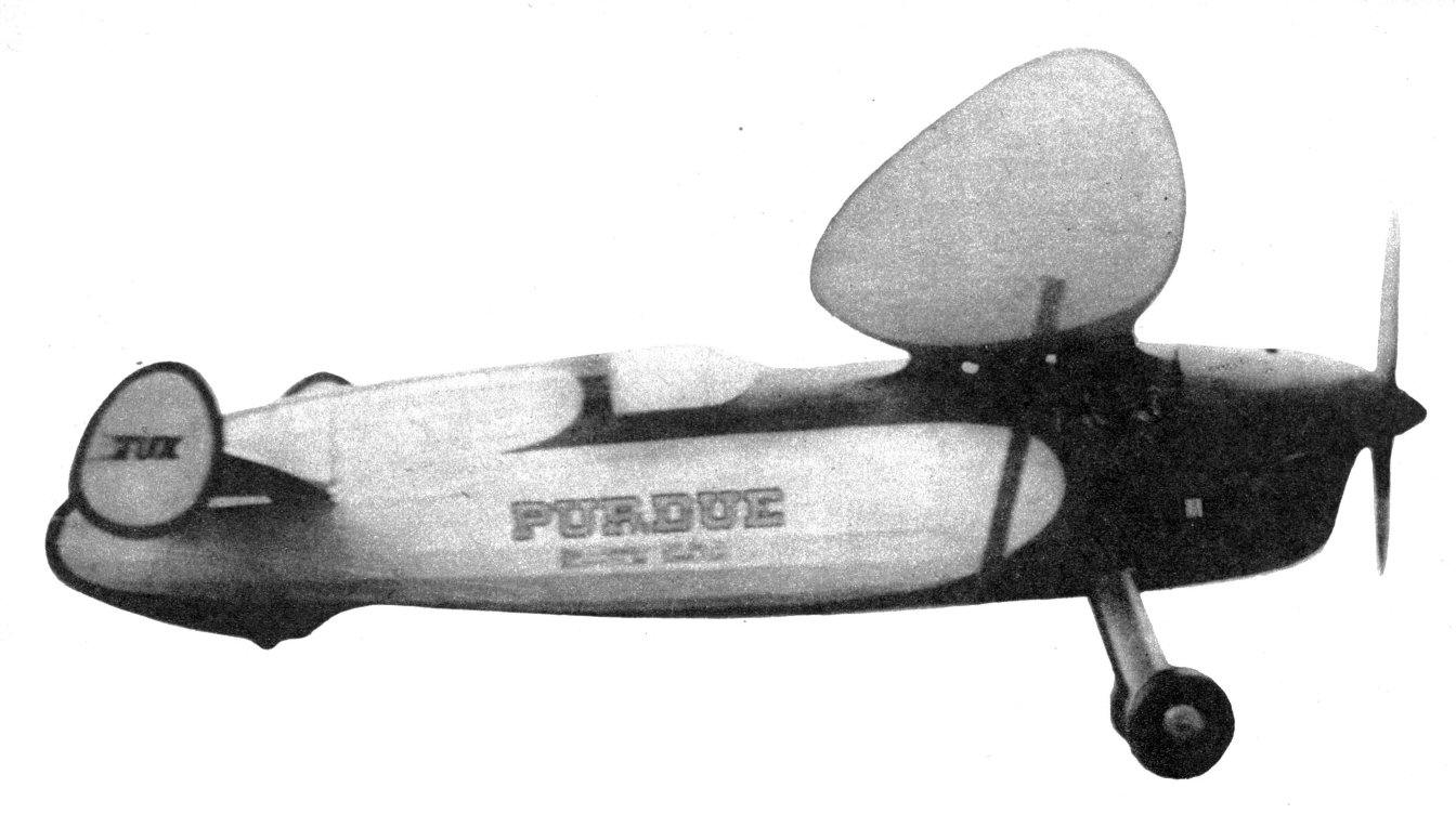
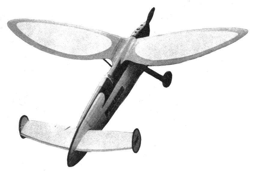
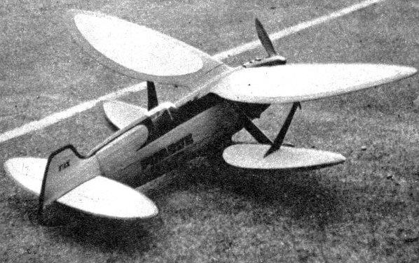
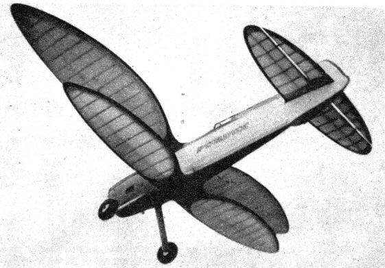
SPORTSTER BY FRED TUXWORTH
For those who like gas models to look like real airplanes, this sturdy performer is just about tops.
THE construction of the Fuselage is quite conventional. It is built in halves and assembled in the usual manner. No fullsize layout is necessary. By placing the cutout formers and keel strips, which are given full size, in their respective positions on a reference thrust line, the lines of the fuselage are automatically decided. The heavy dashes on each former template indicate its position relative to the thrust line. All formers and keel strips are of 1/16" medium-hard sheet, except where otherwise specified. Formers F-10, F-11, F-12 are of double thickness (laminated with the grain running at right angles) above the thrust line to give strength to the wing stubs. By drawing two reference thrust lines and position lines for the formers, both halves of the fuselage may be built at the same time. Place the formers and keel strips in their respective positions on the thrust line. The keel strips should project 1/16" above and below each former. Neglect all hatches and removable sections. These are cut away after the fuselage halves are assembled. The forward 3/16" square and 1/8 x 3/16" members are of hard balsa and are made flush with the edges of the formers with a sandpaper block. The fairing strips are 1/16 x 3/16" medium balsa and are allowed to project 1/16" beyond the edges of the formers so that the covering will not contact the formers -- that is, except where a former is adjacent to the removable section or at the rear of the cockpit. In these cases the spaces between the fairing strips should be filled with small pieces of 1/16" balsa strips to support the covering. The positions for the fairing strips are not shown because even the most careful transfer of formers will produce enough inaccuracies to cause many of the positions to be changed. The individual builder will probably have his own idea of how many fairing strips should be used and the spacing of them. The fuselage section drawing shows the spacing on the original model. Fasten one strip at a time lightly in position on the formers with a few pins and mark its position on each former. (A fountain pen is very good for this and all other markings on balsa.) Remove the strip and cut the 1/8 x 1/16" notches. This matching is best done with a short piece of 1/16 x 1/2" balsa with a narrow strip of very coarse sandpaper cemented to its edge. Use a sawing motion. The planking on the forward end is of 1/16" medium balsa. It is laid over the formers and flush with the edges of the fairing strips. Cover with as wide strips as possible over the flatter sections. This provides the smoothest and fastest results. Where the curves are sharp use 3/32" or 1/8" soft balsa and narrow planks. The contours around the wing stubs are made by cementing the stub ribs in place and filling in between the formers with 1/8" soft balsa blocks. The leading edge of the stubs are formed last by cementing soft balsa blocks in place and cutting and sanding them to shape when dry. When the two halves are completed they may be removed from the assembly surface and the inside of the formers cut away as desired. The formers are left solid up to this stage of construction to provide a more substantial frame to work on. When cutting away the formers, keep in mind the stress on each one. F-11 and F-12, for instance, should be left quite strong because of landing gear stress, and F-13 should be left solid because it acts as the firewall. The cut-away portions are only for accessibility, as the weight saved is negligible. F-14 and F-15 may be cut away to about 1/4" to 3/8" to give ample room for the engine. The two halves of the fuselage may then be assembled and the fuselage completed. The nose block is made from laminated sheets of 3/16" or 1/4" hard balsa. Cement these sheets together to form a block of sufficient size and then lightly cement this block to the forward former. Draw the spinner circle on the front of this block and then carve it to shape. When shaped on the outside, remove it from the fuselage, hollow it only as much as is necessary to clear the engine, and replace it permanently. The removable sections (above the stabilizer platform and the bottom hatch) are made by cutting the stringers away enough to allow a piece of 1/16" sheet to be inserted next to the adjacent formers. Bring these removable sections as near to completion as possible before cutting from the fuselage. This is not only the easiest way to build them, but it insures a good fit. After the bottom hatch is removed, brace F-9, F-10, F-11, and F-12 across the bottom between the lower longerons with 3/16" square strips. The top of the engine cowling is cut away as shown and the top of the firewall is rounded to provide a louver for cooling-air exhaust. The rear of the cowling is also cut away to a thin edge to provide as free an airflow as possible. The landing gear is bent as shown from 1/8" diameter piano wire. Make the center bends first, slip sections of aluminum tubing over the wire, and complete the bending. Bind the landing gear to the two lower 3/16" square longerons. Bind only over the aluminum tubing. Scratching the tubing with coarse sandpaper will give the cement a better hold on it. It will be necessary to cut away a small portion of the planking to bind the landing gear, but this can be easily replaced by inserting a piece of 1/8" sheet and sanding it to fit. The landing gear fairing may be added later. This is made from heavy drawing paper wrapped around brass or tin ribs soldered to the piano wire. Several thicknesses of the paper may be used if necessary to acquire the desired strength. The fairings should fit loosely to allow the landing gear legs to flex; and when crushed or crumpled they may be easily replaced. Rubber cement makes a good adhesive with which to replace fairings. It is well to have some material, already painted, handy for quick replacement. The tail wheel on the original model was a rubber-tired wooden wheel from a toy automobile. Its U-shaped axle is cemented to the 1/16" planking on each side of the tail-wheel cavity. The lower cooling-air exhaust louvers are made by cutting through the cowling and into the firewall as shown. Bend the cardboard to shape for the air scoops and cement in place. The rectangular louver plate may be made from thin aluminum. Cut parallel slots in the sheet and bend the louvers with a pair of flat-nosed pliers; then cement in place. The tubes for the wing shear pins are made from aluminum tubing. On the original model a match stick would fit very snugly into the tubing used. This is suggested, because a good source of shear pins is always available. Roughen the tubing with sandpaper and insert in drilled holes in the indicated positions. Use plenty of cement. Cut the holes under the shear pin tubes to allow for the wing mounting rubber bands. The former at the forward end of the cockpit is used as a template in bending a wire windshield frame. The former may then be cut away and replaced by the wire. The cockpit cover is cemented in place and then the windshield is added. Although a template is provided for the windshield, natural structural variations will make it necessary to fit the pieces individually. Steaming the celluloid will make it very easy to form. ENGINE INSTALLATION The engine mounting is quite unusual. Although the builder may use any kind of engine mount he wishes, the one described has proved very satisfactory and convenient. The engine used in the original model was also often used in another model. The mount consists of a skid to which the engine is bolted securely. The skid is made from two thicknesses of 1/8" mahogany or birch plywood cemented together. The dimensions are determined by the engine to be used. This skid also holds the gas tank and condenser. It is supported in three places in the engine compartment. It is held in place by four heavy wire hooks that are spring-mounted to the inside of the engine compartment. The two forward hooks are of 1/16" diameter piano wire and are hooked directly over the mounting flanges of the engine. Small drill spots in the flanges will keep the hooks in place. The rear hooks are of about 5/64" diameter hard brass wire or brazing rod. They hook into small brass plates mounted on each side of the engine skid. The ignition wires from the fuselage are soldered to the brass plates. Upon installing the engine in a plane the ignition system is completely hooked up when these two hooks are in place. All four of the engine mount springs are attached to wire loops bent as shown and securely cemented to the bottom of the engine compartment. The best positions of the hooks will vary for different engines installed. The chock blocks upon which the engine skid rests should be made from very hard balsa and securely cemented in place. Plastic wood is used to fillet in the blocks. (Use moistened fingers or tools when applying plastic wood.) When the chock blocks are dry the engine skid may be fitted into place. The engine should be mounted to the skid with the line of thrust parallel to the skid edges. All variations in the thrust line should be made in the skid mounting, and it will always be the same no matter how often the engine is removed. The skid is fitted into place by laying a layer of plastic wood over the chock block, moistening the contacting portions of the skid to prevent adhesion, and then pressing the skid into position. Remove it immediately and allow the plastic wood to dry. Several coats of thinned cement will add to the strength of the chock blocks. When all dry the skid will fit snugly into position. Later, if desired, the thrust line may be changed by cutting or building up the rear chock block. Cut any necessary holes in the cowling to allow for the engine controls and gas tank. Some builders may find it advisable to cut a hole in the bottom of the cowling for the removal of the spark plug with a socket wrench. Give the entire inside of the engine compartment several coats of shellac. The spinner is made from disks cut from hard sheet balsa and cemented together as shown. It is made in two parts; the back section is clamped between the drive plate and the prop hub, and the spinner cap is fastened with two wood screws to the sides of the prop hub. After having built quite a few spinners, I found this method most satisfactory because it can be rapidly adapted to any propeller. WINGS In building the wings, first lay out a spar line and then rib position lines at right angles to it. No further layout is necessary. Cut out the leading and trailing edges and the tip and root rib. Lay these in their correct positions on the drawn position lines. By using the chord dimensions and by carefully cutting the edges, the wing can be built quite accurately. Assemble the edges of the wing first. See that the joints are good fits; this may be done with a sand block. Use two applications of cement; the first should be of thinned cement and allowed to dry without assembling the parts. (This extra penetration will provide a much stronger joint.) When the edges are assembled but still unshaped in section, the rest of the wing is built. The lower cap strips are straight pieces and are laid flat. The spar is placed in position on these strips and then the upper cap strips and false ribs are added. The upper cap strips and false ribs are cut from medium 1/16" sheet quarter-grained balsa by cutting along the edge of an aluminum rib template with a razor blade or knife. After making each cut, move the template down 5/32" and make another cut. Mark the position of the spar on each strip. The false ribs can be cut with the same template by merely using that portion forward of the spar position's mark. In assembling these upper cap strips a little judgment is required to turn out the best airfoil; trim the ribs at both the leading and trailing edges and always place them so that the spar position mark is always directly over the spar. The cap strips need only be held in place at present with a small amount of cement, as all joints are recemented later. The auxiliary spar is a strip of soft 1/16" sheet about 3/8" wide. It is intended to provide a little rigidity to the wings and also to brace the ribs. Slip it in between the cap strips and push it back until it contacts both the top and bottom strips, then cement it in position. It will form a curve much like that shown in the drawing. When the cement is dry the wing may be shaped. Trim the edges roughly with a knife and finish the entire wing with a sandpaper block. Work it lightly over the ribs and edges until the joints and contours are smooth. When the shape is satisfactory, every joint in the wing should be gone over at least once with thinned cement. By using a brush this may be done quite rapidly. Apply at least two coats of cement to the leading and trailing edge joints. Joints made in this manner provide a maximum of strength, and if the cement has been thinned sufficiently they will not show through the covering. Locate the positions for the wing peg tubes in the root ribs. Drill holes and insert one-half-inch sections of aluminum tubing of the same diameter as used in the wing stubs. Make the wing strut fitting by soldering 1/8" lengths of 1/16 " diameter brass tubing to 1/8 x I" strips of brass or tin. Bend these so that they fit over the rib and along the bottom edge of the spar and bind them with linen or silk thread and cement. The rubber mounting hooks should be bent as shown and securely cemented in place. The wing is held in place by stretching rubber bands from the hooks on one wing, through the holes in the wing stubs, to the hooks on the other wing. Use a long piece of 1/16" diameter piano wire with a tight hook in one end to pull these rubber bands through the fuselage, and stretch them in position. The wing struts are made from very hard balsa and are streamlined in section. The fitting on the wing end is a piece of piano wire bent and mounted as shown. The free end of the fitting is bent parallel to the wing lower surface to allow the strut to fit closer. The hook in these fittings makes it necessary to twist the strut into position, and then when the other end is fixed the wing end cannot become disconnected. The fuselage end of the strut is provided with a short section of 1/16" diameter aluminum tubing and a rubber hook. The lower fuselage longeron has a similar piece of tubing in it. A common pin, bent to suit, is used in this tubing to hold the strut in position, and rubber bands are stretched from one wing strut hook, under the fuselage longerons to the other wing strut hook. This arrangement for mounting the wings allows a very strong connection that will give in any direction in case of a crack-up. TAIL SURFACES The stabilizer construction is very similar to that of the wings. The ends of the spar and the leading and trailing edges are allowed to project a short distance beyond the tip ribs. The fins fit over and are cemented to these projections. This eliminates the typical warping characteristic of this type of fin. As in the wing, the stabilizer is sanded to shape after assembly, and all the joints are recemented. After the dihedral is put in, the center section is covered with soft 1/32" sheet. To hold the stabilizer in place on the fuselage, cement two pieces of piano wire across the underside of the stabilizer platform to act as rubber hooks. Place one under the leading edge and one under the trailing edge, and allow about 3/8" of the ends to project through the fuselage sides. By using 1/4" sections of aluminum tubing in the platform and pegs in the stabilizer, the position of the stabilizer can be made very constant. The section of the fuselage which fits over the stabilizer is finally cemented to the stabilizer, but it is best to hold it in place with pins until the model has been flown and the best angle of incidence decided upon. COVERING AND FINISHING The builder may use any kind of covering material he wishes. Bamboo paper was used on the original model because of its toughness; however, its weight and the difficulty of applying it on the curved fuselage are disadvantageous. Use narrow strips of tissue over the wood-covered portions to give them a smooth appearance when doped. Dope the entire model with one coat of clear, and as many coats of colored dope as necessary, to give the desired finish. Sanding with fine sandpaper between coats will improve the surface considerably. Scanned from November, 1941
|