|
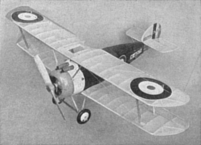
Building the Sopwith Camel PAUL W. LINDBERG Model editor and designer for POPULAR AVIATION
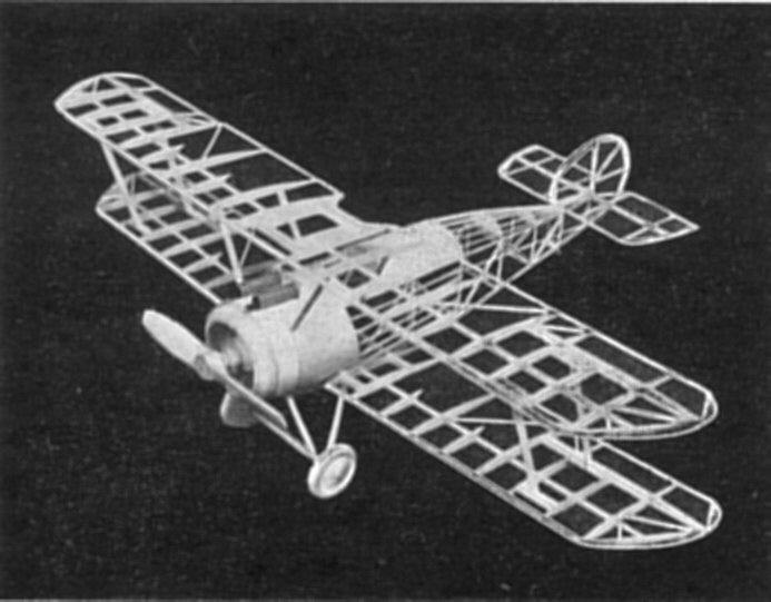
OUR readers were so pleased with the last wartime model and so, by popular request, we have drawn plans for an exact scale model of the Sopwith Camel F-1. The construction of this model is very simple. The weight of the model has been made as light as possible in order to obtain good flying qualities. The model is very stable and will fly a long distance. All details, such as shock-absorbing, landing-gear, movable surfaces with aluminum hinges, correct markings, etc., have been carefully carried out. All dimensions can be quickly and accurately determined, by placing a ruler on part to be measured. If you wish a larger model, multiply this measurement by the amount of increase. COLOR SCHEME Fuselage-blue tissue; front section painted white; see plan. Cowl-red. Wings and tail surfaces-yellow. All struts - natural wood color. Please note: to eliminate weight, the model is covered with colored tissues and not painted with colored dopes. CONSTRUCTION OF FUSELAGE First, place waxed paper on top of plan to prevent parts from sticking to paper. The fuselage sides are built from 1/16-inch square balsa. The longerons, verticals, diagonal braces, etc., are held in place until securely cemented by inserting straight pins on either side of strips wherever needed. When the two sides are completed, the cross-members are cemented into their proper locations. Check carefully front-to-rear for alignment. Cut the formers from 1/32-inch sheet balsa and cement in their respective positions as shown on the plan. The position of the stringers are clearly shown on the formers. See plan. Work stringers from front to rear and check carefully to see that they have the correct spacing. Section of fuselage from formers 1-11 and 10, to formers 8 and 8, is covered with stiff paper. Formers 3 to 4 and 4 to 5 are covered with separate pieces of stiff paper. CONSTRUCTION OF WINGS Cut all ribs from 1/32-inch balsa. Pin center spar in position on the plan. Now, cement ribs in their proper locations. The leading and trailing edges are cut and sanded to shape and cemented to the ribs. The upper and lower panels carry movable ailerons which are a great help in controlling the flights. Make wing tips from 1/16-inch thick balsa. We highly approve of this type of wing tip, because it is much easier to construct and neater in appearance. ELEVATOR AND RUDDER These are built on the plan and are made of 1/16-inch square and 1/16-inch sheet balsa. No trouble should result here, because they are very simple to construct. MOTOR The motor cylinders are built up from sheet balsa and pieces of paper. Study plan carefully. CRANKCASE This is built from several pieces of balsa. See sectional view on plan. COVERING THE MODEL Apply tissue to the various framework members, using a light grade of model airplane dope to fasten it to the outer edges. Stretch tissue as tightly as possible to remove all wrinkles. When edges have dried, apply coat of water to tissue. When all water has dried completely, tissue will become taut. May we suggest that you pin wings, elevator and such upon a flat surface to keep from warping. FINAL ASSEMBLY After all struts, etc., have been cut to size, you can assemble the wings to the fuselage. Next, install elevator and rudder. Grey thread is used for all bracing and flying wires. Force needle and thread through trusts, and hold thread in position with drop of cement. Other small details are clearly explained on plan. TESTING AND FLYING THE MODEL Use 6 strands of 1/8-inch flat rubber and attach flying propeller to nose. To test proper gliding angle, gently launch model over tall grass. Add weight to nose until the model will glide on an even angle. You can now wind the propeller for a test flight. Any adjustments regarding the flight of the model can be made through the use of movable control surfaces. END. Scanned From Popular Aviation
|