|
A flying model of the latest BY WALTER KAHN
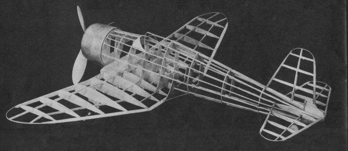
Above -- The completed framework reveals the exactness
with which the real ship has been duplicated.
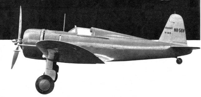
DESIGNED to conform with the United States army specifications and listed by the manufacturer, Chance Vought, as an export model, the V-143 is a challenge to any other ship within its class. Capable of doing close to three hundred miles per hour, the V-143 is easily maneuvered and can ably defend itself. The construction of the model is simple, entailing only the primary steps of model-aircraft building. Before attempting to build the model it is advisable. to read and thoroughly digest the directions. By doing this, costly mistakes will be avoided. CONSTRUCTION Fuselage may either be constructed in two halves or else with complete bulkheads. The bulkheads are, all except #1, cut from 1/16" sheet with the grain running vertically. In cutting out the bulkheads only the four main notches need be cut. The position of the intermediate stringers should be marked. This procedure is suggested to enable proper alignment of the stringers. After the four main stringers are secured in place the notches for the intermediate stringers are cut with a sliver of a two-edged razor. The complete cockpit cover frame is made from 1/32" square bamboo. This frame is covered with a sheet of celluloid. The portion between #4 and #5 is covered with 1/32" sheet, and made to fit as shown on the top and side view. The tail block is cut to the shape shown on 3. It is hollowed out to as thin a wall thickness as possible. The wood for the tail block must be the lightest obtainable. The block is not cemented in place until the stabilizer is secured. Wing construction follows the same general procedure for building most model wings. The wing is constructed in one panel. Because of this it is necessary to trace the half of the wing shown and use it as the other half. The complete layout of half the wing is gotten by connecting Sheet 2 with Sheet 4. The ribs are all cut from 1/16" sheet. The wing is constructed on the plan itself with the various parts held in place by pins until the cement has set. As the wing is tapered, both top and front, it is necessary to taper the leading edge and spars accordingly. It is suggested that the parts first be roughly shaped and glued in place. After the wing is removed from the plan the parts are then sanded to a smooth finish. The wing tips are of bamboo and can best be formed over a flame. If desired they can be wound with thread at the leading and trailing edges. Special attention should be given to the center block. The block is not hollowed out as the bulk is required to balance the completed model. The cross-sectional shape is shown on the plan. It follows that of the wing section, except it is extended farther forward of the leading edge. After the wing is completed, the outer wing panels are broken at the point of the solid center block to form the 1-1/4" dihedral. The joints are reglued. Tail surfaces. The construction of both the rudder and stabilizer is like that of the wing. It is important that the lightest balsa wood be used in its construction. (Due to the large moment arm of the model a heavy tail will throw it out of complete balance.) The spars used are 1/16" balsa rounded and are made to run through the ribs as shown. The ribs of the tail are first cut roughly to a streamline shape. After the tail is completed they are sanded smoothly. The tips are of bamboo. The bamboo used should not be greater than 1/32" square. Landing gear construction is extremely simple, as it consists entirely of a single strut attached to the wing as shown. The shape of the strut is shown on Sheet 2. The strut is made in two parts and attached by inserting the lower part into the top. The axle is a piece of music wire bent to the shape shown; it is glued and wound with thread for security. The side cover of the strut is cut from 1/16" sheet balsa and cemented to the strut. Cowl shape is shown on Sheet 1. It is hollowed out to house a 2-1/2"-diameter celluloid engine. The cowl is held to the model by slipping onto a special Bulkhead # 1 cut from 3/16" stock. Flying propeller is shown on Sheet 5. It is a three-bladed propeller. Each blade is carved separately and inserted into a three-bladed hub as shown. Care must be taken to see that all the blades are attached with the same pitch angle, otherwise the propeller will not-track. If desired, a scale propeller may he used. The side view of such propeller, a Hamilton Standard, is shown on Sheet 1. The front view is of conventional metal propeller shape. Motor stick is 1/8 x 1/4" stock. It is attached to the celluloid engine as shown. The engine is held to the cowl by small drops of cement on each cylinder. The propeller shaft is then passed through the rear of the engine. A ball-bearing washer is placed on the shaft. Following this the propeller is placed on. The shaft is bent to the shape shown on Sheet 5 and forced into the hub of the propeller. A drop of glue will secure the shaft to the prop. It is important that the shaft be lined properly. This should be checked. The rear hook is bent as shown. It is attached to the motor stick by inserting the prong end of the hook into the stick, wound and glued. COVERING THE MODEL Because most of the parts are attached directly to each other they can be covered separately. The model is covered with superfine tissue. The portion of the fuselage adjacent to the wing incorporating the fillet should be covered with the wing in place. This will result in a neater fillet. The manner of covering is left to the builder, for no two builders will agree as to the correct manner. However, this might be said: The grain of the paper should run in one direction. After the parts have been covered a thin spray of water should be applied to shrink the paper taut. A few coats of banana oil will preserve the tautness of the paper and protect it from changes in weather. ASSEMBLY The wing is first attached. It attaches directly to the fuselage, with Formers #5, #6, and #7 lining up with the center-section stringers. A piece of bamboo, as shown on Sheet 2, is used as a fairing strip from the wing to the fuselage. With the wing set, the center section can now be covered with the portion of the fuselage adjacent to the wing. The rudder is next attached. It is glued directly to the top stringer. To counteract torque the rudder should be offset slightly to the left -- looking from the cockpit. The stabilizer is next glued in place. It is advisable not to secure it permanently until the model has been flown. The tail block is now glued in place and finished off to a smooth surface. FLYING THE MODEL The model is powered with four to six strands of 1/8" flat rubber. The model is first glided to determine its balance. If it stalls, weight must be added to the cowl. If it dives, which it is likely not to do, weight must be added to the tail. The stabilizer setting should be zero. With the model balanced, give the propeller about thirty winds and hand-launch. If the model tends to stall, increase the stabilizer angle; if it dives, set it at a negative angle. The settings should be slight as they will be found most effective. The model should be fully powered to about 150 winds on four strands, somewhat less for six. Scanned from December 1939 |

