|
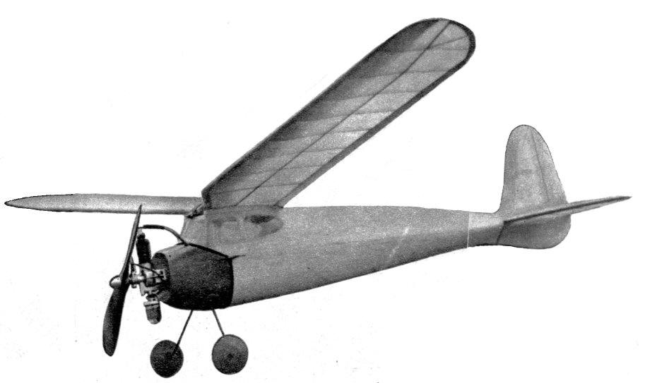
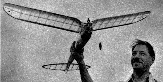
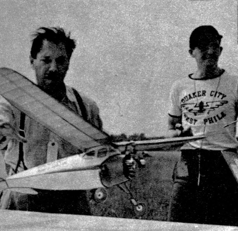
THE MOLECULE
With the advent of improved tiny engines, Class A gas models are coming into their own in aeromodeling. As with everything in life, competition results in improved products for the ultimate benefit of the consumers --that's us, the model builders. Having used many engines, the writer has found much satisfaction with the Atom, the smallest and lightest production engine. The Molecule was designed specifically for this superlight engine, and this accounts for the low total weight of twelve ounces. At the official Eastern States Gas Model Championship the ship proved itself by spectacular performance. By winning first place and setting a sensational record, the ship lifted Class A modeling to a new level and gave it the respectability and recognition on par with other classes of powered model flying. It wrote finish to flights of a few seconds that were predominant hitherto. The influence of this method of sheet balsa monocoque construction is being felt in all modeling circles. Several commercial models have adopted this system, and the Molecule is the latest example employing several new wrinkles. While the engine used is responsible for a greater rate of climb, the inherent characteristics of the Molecule make possible the flat glide and soaring ability. BODY Make the lower half of the body first. Study the top view and fuselage detail and assemble the two longerons with all the cross braces. Although the plan does not show a cross brace at the very front, cement one in to bring the total width up to 2-5/8". This will be removed when the body is completed. Cut out the two blanks, pin them together and sandpaper to uniformity. Look over the two curves and see that there are no wavy or uneven sections left in the outline. Shape two of each of all the formers out of 1/8" sheet balsa. Now lay the two blanks down so that the underslung rudders "toe" together, and brush clear dope on the entire surface up to the point where the rudders begin. Make sure that the dope covers evenly. A second coat is applied after ten minutes. From this time on the two blanks will slowly curl up. The longer the drying period the more curve will be acquired. Experiments showed that this gradual warping will go on for days and days if it is not stopped. Our purpose is to get only a sufficient curve to fit the formers, so when the curvature is slightly less than Former 1, glue and pin in this part and follow up with 2 and 3. Never dope a pair of blanks before you are about to take part in a long game of checkers, unless you expect to see a balsa pretzel when you get back to your model. In fact you should not stop working until the whole lower half is completed. Now take the two blanks and cement them to the side of the longeron assembly. Use plenty of pins and do not forget that the longeron is only halfway in (1/16"); the other half sticks out to accommodate the top half of the body. Next pull the bottom seam together. Although you may be able to do it with pins, we strongly recommend the use of cellulose tape for a perfect job. About ten 3" -- long pieces will hold the seam together. Cement on the inside of the body, except the rudder part, which is cemented on the outside. Use this same method in creating the top half of the body. Naturally this seam is very hard to cement on the inside, so we will do it on the outside. On any outside cementing be very careful not to spill cement on the surface -- and use it sparingly so as not to spoil the appearance of the body. Build up the cabin roof out of 1/8" balsa. (Three pieces -- the two sides and a front cross piece.) Cut out the tilted former in front of the cabin, which is the same as two No. 1 formers in one piece. Pin and cement this former at the same angle as shown. Notch in the body top behind the cabin roof about 1/4" deep and cement the roof into place. Now fasten the three cabin struts, paying special attention to the line-up of the roof from every direction. The cabin blanks need only one coat of dope, since the bulge at this point is very little. The cabin windows are cut after the blanks have been cemented into place. A small brace between windows will help to stiffen this spot. Use heavy celluloid for the windows. Smooth out the entire body with fine sandpaper Finish by brushing one or two coats of microfilm solution on the surface first, followed up with one coat of varnish. It is important to have some finish on the body which will withstand the rotting effect of gas and oil. But stay away from dope and paint, as they will put the body out of shape in time. The microfilm solution and varnish are absolutely harmless in this respect. Make the nose the following way: Copy the two front formers onto a piece of paper. Cut each piece 3/32" smaller all around. Cut 1/2" off the curvy part of each in a straight line. These cut-offs will be filled in with a solid block. Cut out the formers of 1/8" sheet and leave them solid. Now cement the two together at the same angle as the front of the body. While an auxiliary 1/4" x 1/4" holds the front former in place, plank the sides with 3/16" soft balsa and put solid blocks on top and bottom. Carve and sandpaper to shape. Use clear dope and paint inside and out in order to make it gas-proof. Two bamboo tracks anchored in the bottom of the nose support the coil. The battery box is made of hard 1/16" sheet balsa and cemented firmly. The landing gear is of 1/16" piano wire faired in and reinforced with a large-face brass bushing on each side of the nose. The motor is mounted on two aluminum brackets which in turn are screwed to the front former. I have used a sawed-off Austin timer -- but, shifted a little forward, even a fullsize one will fit in. Solder all the connections into a firm joint. To avoid losses through interference, the high-tension wire is brought through a slot between the nose and the cabin front. The whole nose is held firmly to the body by rubber bands on each side. Provide piano-wire hooks for this purpose, both on the nose and body. WING AND TAIL The wing is made in two halves. Cut out all the ribs for the straight part of the panel. Pin the trailing edge down and butt-joint the two end ribs. Now slide the spar through the notches and fasten the leading edge. Follow with the rest of the ribs. Bend the bamboo tips above the gas range, and notch them in place. Fit in the smaller tip ribs, which are sanded lower and lower toward the tip. The front cut-out ring may look odd to some, but it is the only way to preserve the cabin position. The tail employs no spar. The outline is cut out to shape and assembled. Flat balsa ribs are set in, whereupon the edges are sandpapered into a streamlined section. The rudder tab is solid balsa hinged with small aluminum pieces. Cover all the surfaces with single Jap tissue. A couple of coats of dope should make it water and gas-proof to a reasonable degree. The wing and tail units are fastened with rubber hands. FLYING Glide the model without the prop, whose weight is replaced with a rag bundled around the motor. If there is any incidence change necessary, do it on the elevator. When the hand glide is perfected, leave the rudder in straight position, open the motor to about seventy-five percent and hand-launch the model ten to twenty degrees off the wind to the left. If it does not continue to turn in the same direction and stalls around under power, give it one-eighth-inch left rudder the next time. All adjustments should be carefully considered before being put into effect. My original model has made hundreds of flights without damage. Scanned From December 1939
|