|
Home-made Wind Tunnel Part 2 BY R. C. CLIFFORD Last month the author presented plans of
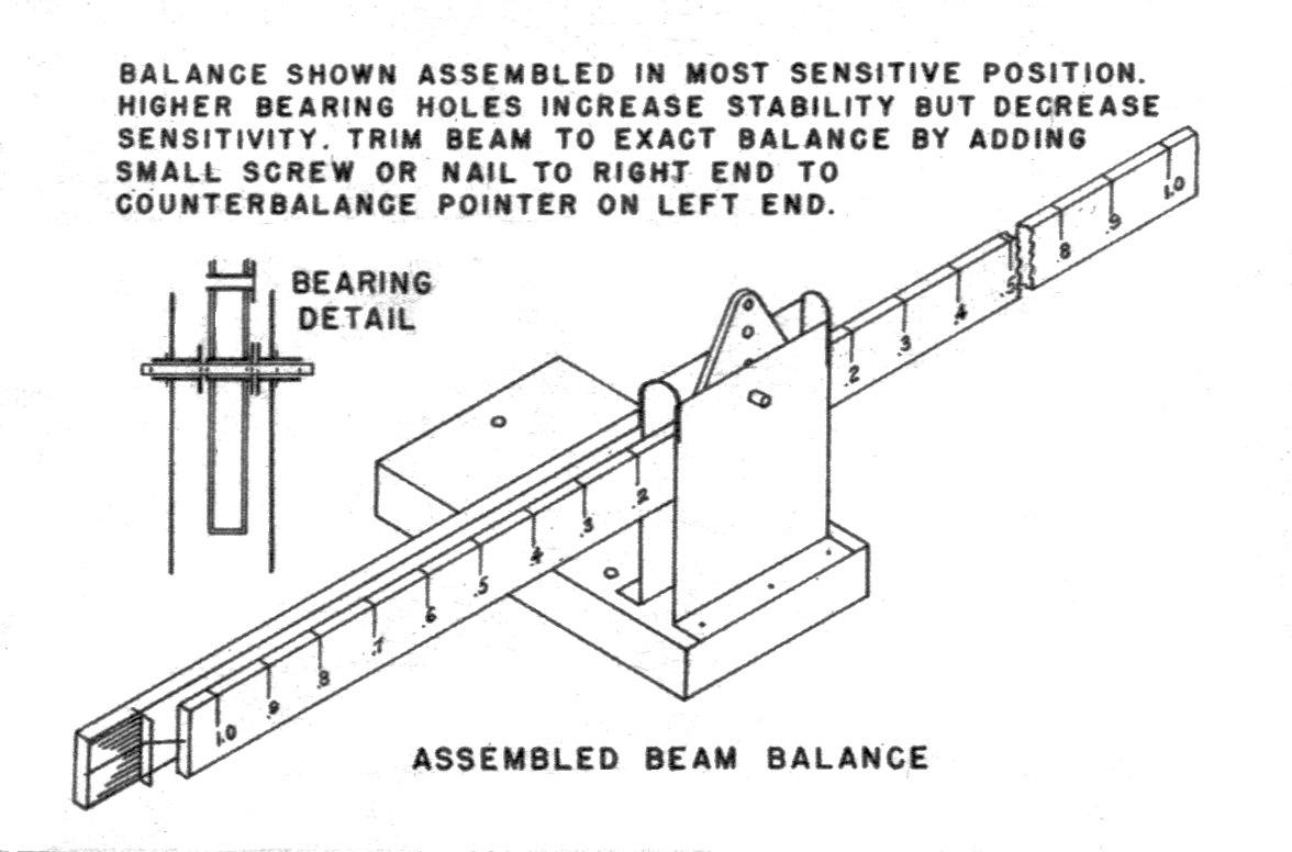
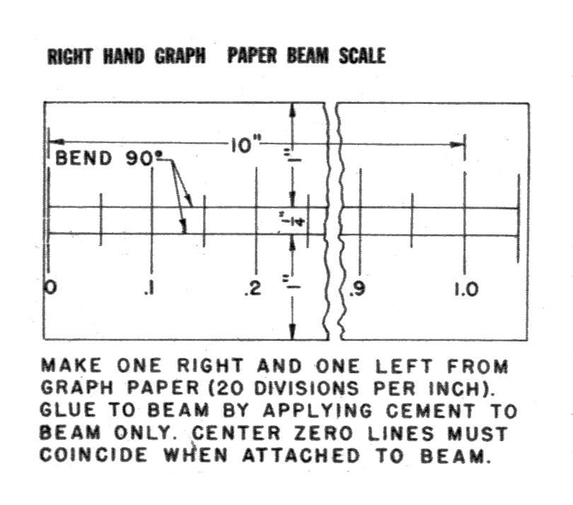
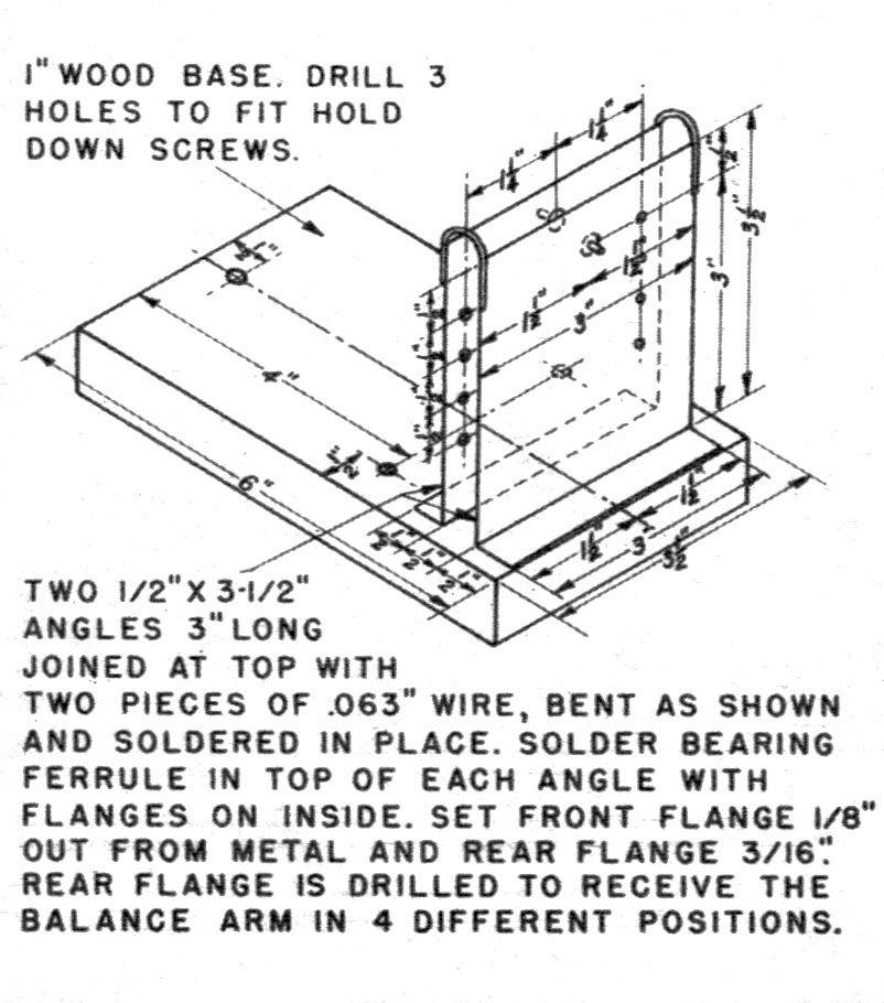
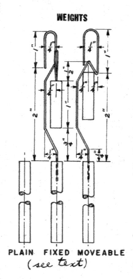
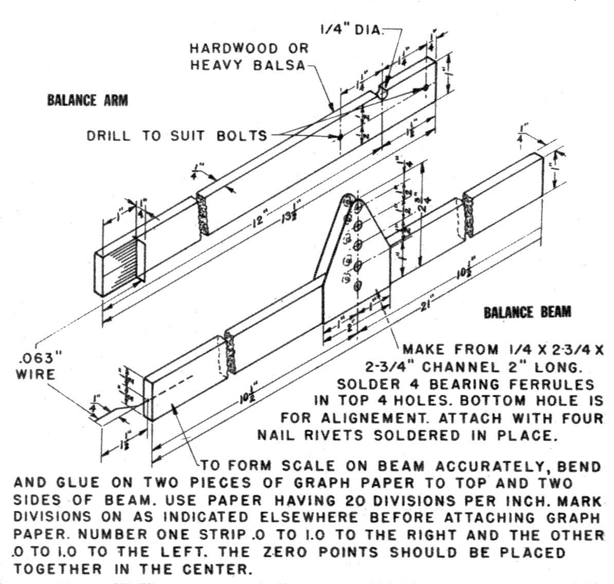
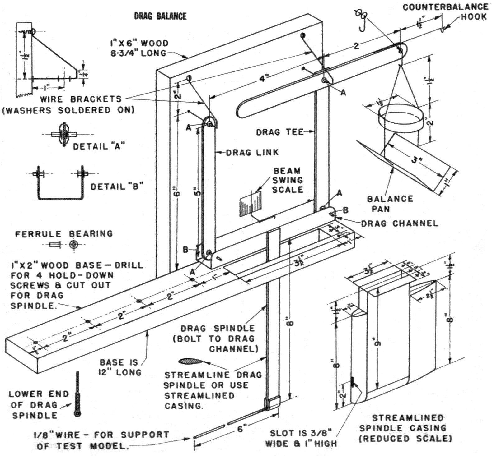
a practical wind tunnel. A WEIGHING balance is required for use with the tunnel air balances. If one is not available, the simple beam balance shown is easy to make and ideal for wind-tunnel work. As most chemical balances weigh in terms of grains or grams instead of decimal parts of an ounce, the beam balance will be found more convenient to use than any pan-type balance that might be available. A set of sixteen one-ounce weights is necessary to give results at one-ounce intervals, and the beam balance is used to get the decimal part of the weights. The ten inches of graph paper having twenty divisions per inch will give 200 divisions, each representing 1/200 ounce, or .005 ounce. A table is provided which gives the length of various shapes of steel bars that weigh one ounce. The material should be cut slightly long. The co-operation of a high-school chemistry teacher, a high-school physics teacher, or a druggist is necessary to get the use of a pan-type balance to finish the steel weights accurately down to one ounce in weight. A one-ounce laboratory weight is placed on the right pan of a chemical balance and the left pan is filled with weights until the balance is accurately trimmed. Then the laboratory weight is replaced with a steel weight and its excess weight is filed off until the pans are again in balance. Repeat for all the steel weights. If, when through, the one-ounce laboratory weight can be replaced on a "balanced" balance with each of the steel weights without changing the trim of the balance, then the steel weights are just as accurate as the laboratory weight plus or minus the sensitivity of the balance. The sensitivity of a balance is the largest weight that can be added to the pan without changing the trim. It is negligible for a commercial chemical balance designed for weighing up to one pound. When weights are provided with a wire handle, the weight of the whole assembly must be one ounce. The beam swing scale is a small piece of heavy drawing paper with parallel inked lines accurately spaced 1/8" apart, as shown, and glued on the end of the balance arm. The lines provide a convenient means for observing when the beam is in balance and swinging equally on both sides of the long horizontal center line. Bearings in the balance beam bearing channel are ferrules 3/32" in diameter by 5/16" long soldered in holes drilled on a vertical center line. The channel is attached on the beam after the paper scales have been glued on and allowed to dry thoroughly. The center line of the bearing channel must line up accurately on the zero line of the scale as observed through the bottom hole on the channel. After final assembly, the beam must be balanced by adding weight to the light end (in the form of small nails or screws) or by cutting off some material from the heavy end. The two bearing ferrules in the base angles should be soldered in place after final assembly of the base while they are held in line with a straight, tight-fitting wire threaded through the holes. Allow about 1/64" for end play over the width of the bearings on the beam. Use a bearing wire for final assembly that is a loose fit in the ferrules. Upon completion, the beam should oscillate freely when balanced. All friction caused by tight bearings, no bearing end play, poor bearing line-up, et cetera, must be eliminated. A drop of fine oil will help matters. The beam balance is shown assembled in its most sensitive position. The stability of the beam will be increased and its sensitivity will be decreased slightly by using the higher bearing holes. Beam must be trimmed to balance without load. (The wire pointer in the left end of the beam will need a small screw or nail in the right end to balance the beam.) DRAG BALANCE The drag balance is a fairly simple affair. The horizontal base consists of a 1" board 2" wide and 12" long. Four holes are drilled to receive hold-down screws and a rectangular hole 3/4" wide by 3-1/2" long is cut to receive the streamlined drag spindle casings. If the casing is not used, the hole should be made 1/2" wide by 1-1/2" long. The vertical board of 1 x 6" wood 8-3/4" long is attached to the side of the horizontal base as shown with three long woodscrews. To keep the wood from splitting, pilot holes should be drilled to receive the wood screws. After assembly, a line is marked accurately on the vertical board 6.00" above the horizontal base (dimensions given in hundredths should be accurately maintained). Two holes 5/32" in diameter should be drilled on the line 4.00" apart to receive the ends of the wire brackets. The bearings of the balance are made of brass ferrules 3/32" in diameter and 1/4" long, soldered in place. The partially closed end of the ferrule must be filed off or opened up by forcing it on a 3/32" rod and sliding it up and down on the rod until it can be moved without friction. The front drag link is a piece of iron bar 1/16" thick, 1/2" wide, and 5-1/2" long with two 3/32" holes drilled accurately 5.00" apart on the centerline of the bar. The ends are rounded off with a, file to a radius of 1/4" centered on the drilled holes. Two ferrules are soldered on each end of the link as shown in Detail A. A 3/32" wire should be threaded through the ferrules when soldering to assure proper alignment. The top bar of the drag tee is made exactly like the drag link. The vertical bar is also similar to the drag link, except that the top of the bar is left square. The vertical bar is soldered to the middle of the top bar at right angles to it as shown. Drill a 3/32" hole through both bars at the intersection of their centerlines. Drill a 3/32" hole on the centerline of the vertical bar 5.00" below the first hole. Drill a 3/32" hole on the centerline of the right arm of the top bar 2.50" from the first hole. Solder two ferrules on each end of the vertical bar as shown in Detail A. Make a balance pan hook for the third hole as shown by the detail. The washers should be soldered on the 1/16" wire hook to give about 1/32" of end play over the thickness of the bar. The drag link and drag tee are supported by two wire brackets. One end of the wire is a force fit into the drilled holes on the top of vertical board base. The other end of each bracket fits around a wood screw. One washer is soldered on each bracket to bear up against the wood and hold the wire in position. Two other washers are soldered on each bracket to locate the drag link and drag tee 1" away from the wood. The distance between the washers should allow the top bearings of the drag link and the drag tee 1/32" of end play. Use the largest size of wire for the brackets that will give a free, frictionless fit in the bearing ferrules. The drag channel is made from light gauge tin as obtained from a five-gallon oil can. It is made 3/4" high, 3/4" wide, and 4-1/2" long. Two holes 7/64" in diameter are drilled in each side 1/2" from the back of the channel and 4.00" apart. To drill them opposite, locate the holes on a line at each end that is scribed around the three sides of the channel with the aid of a square. Solder a bearing ferrule in each hole with the flanges toward each other as shown in Detail B. The distance between flanges should be 1/32" more than the width of the bottom bearings on the drag link and the drag tee. Have a 3/32" wire through opposite ferrules when soldering them to keep them lined up. Solder a 1/16" wire pointer on the rear side of the drag channel as shown so that the vertical end is about 1/16" in front of the balance swing scale. The swing scale is a piece of heavy drawing paper about 1" square with vertical lines 1/8" apart drawn as illustrated. It is glued to the vertical board to show when the forces on the drag channel have been balanced. With lines marked as shown, it is easy to tell when the channel is in balance and swinging an equal distance each side of center. The vertical drag spindle is a piece of steel bar 1/16" thick, 1/2" wide, and 8-3/4" long. It is bolted to the middle of the outside leg of the drag channel by four small model bolts. A piece of tin 1/2" wide and 1-1/2" long is bent as shown and soldered to the bottom of the spindle to give a tight-slip fit over the 1/8" diameter wire that extends 6" forward to support the models being tested. If the drag spindle is not inclosed in a streamlined housing, it should be filed to a streamlined cross section as shown in one of the detail sections. The basic part of the streamlined housing is a metal channel 3/4" wide, 3-1/2" deep, and 9" high, with two 3/4" legs on top bent over at an angle of 90°. After slipping the channel into the rectangular hole in the horizontal base and attaching it with wood screws to the base, the bottom of the channel is plugged with a piece of wood 3/4" wide, 1" high, and 3" long with its bottom end rounded off to form a cylindrical surface 3/4" in diameter. The nose piece is shaped to a streamlined form from a wood block 3/4" thick, 1" wide, and 8" long. The bottom of the nose piece has a vertical slot 3/8" wide by 1" high (channel has similar slot) for the 1/8" wire which projects forward through the slot to support the test models. The tail piece completes the streamline form and is made from a block of wood 3/4" thick, 2-1/2" wide, and 8" long. The bottom of the nose piece and tail piece are rounded off to streamline into the bottom piece of wood. Use wood screws to attach the nose, tail and bottom pieces to the channel. The tail piece should be easily removable. A counterbalance hook is soldered on the top of the drag tee as shown. Make it of 1/16" wire. The drag pan is made of a light gauge angle 1 x 1 x 3", a light tin pan about 1-1/2" in diameter and 1/2" deep, and some 1/16" wire bent as shown and soldered to the pan and the angle. When completed, the balance must oscillate freely when in balance. Any friction caused by pressure on the ends of any bearing, by any tightfitting bearing, or by poor alignment and binding of any bearing must be corrected by reworking or by making new parts. MOVABLE WEIGHTS FOR BALANCES Make sixteen plain 1-ounce weights; a 1/4, 1/2, and a 1-ounce movable-type weight; a 1/4, 1/2, and a 1-ounce fixed-type weight. Length of Cold Rolled Steel Stock Weighing One Ounce
Scanned from June 1942 |
|||||||||||||||||||||||||||||||||||||||||||||||