|
Home-Made Wind Tunnel Ideal for model clubs, this practical testing apparatus
gives good results.
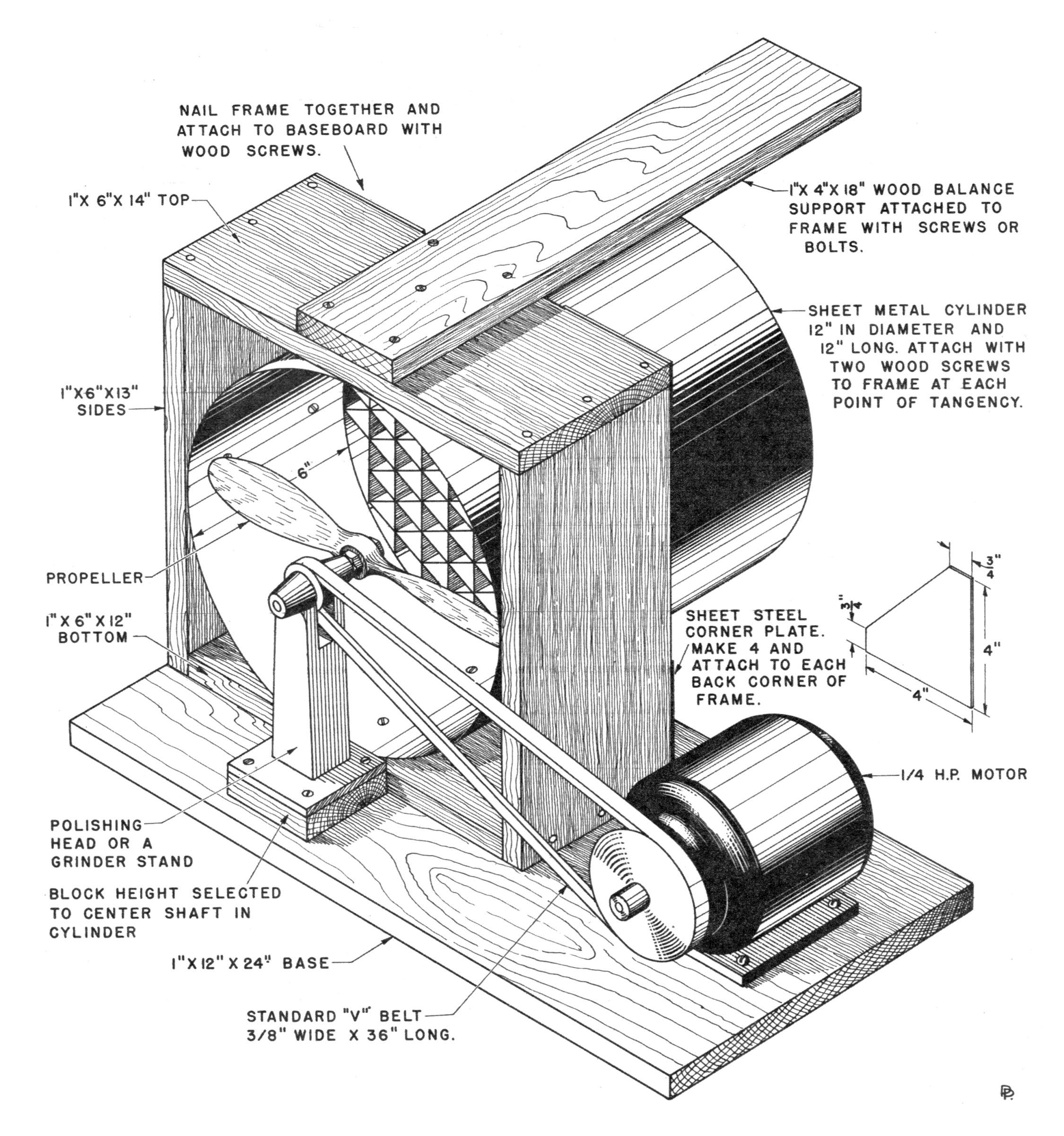
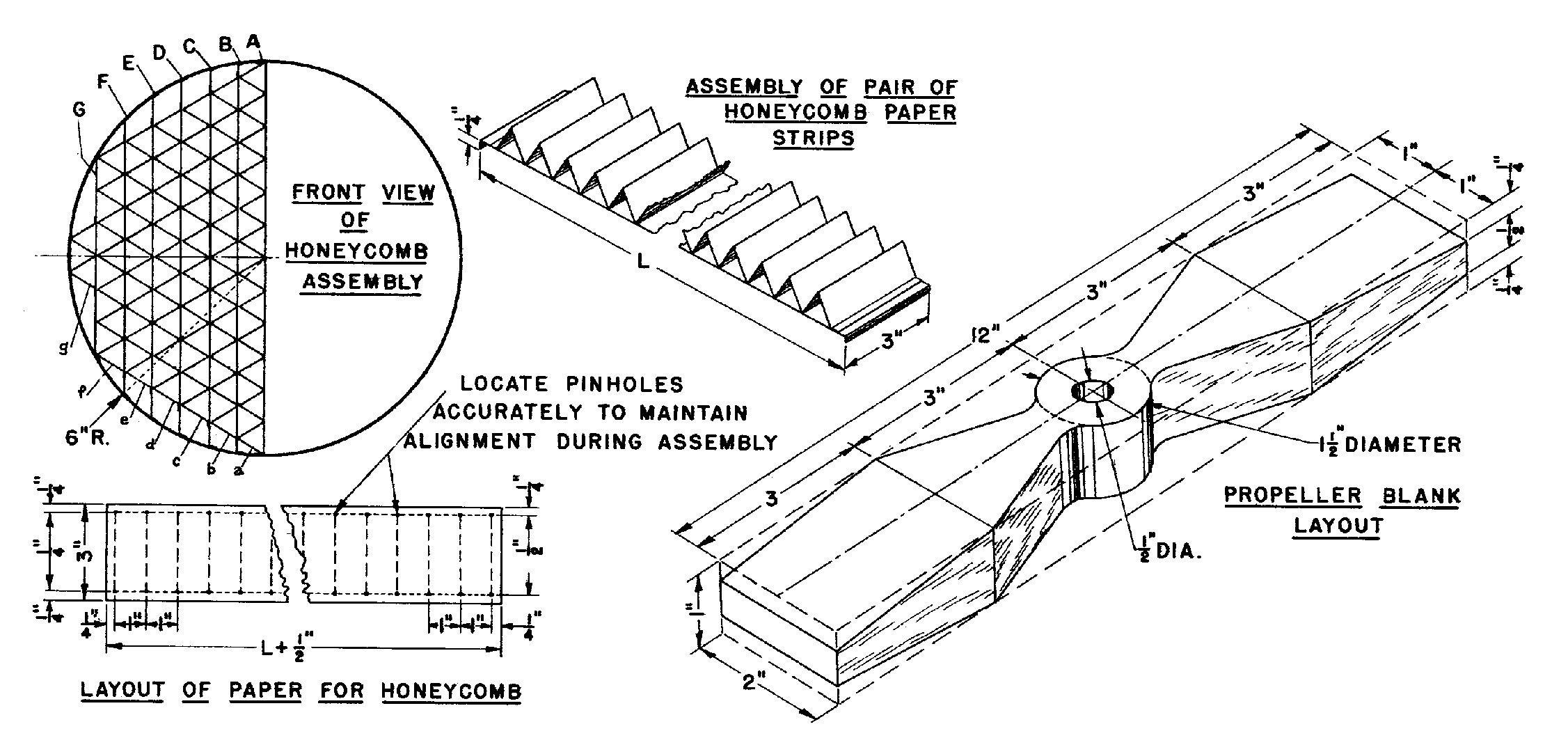
THIS report covers the construction of a 12" diameter wind tunnel. A drag balance and a compound lift-drag balance suitable for educational purposes to demonstrate and verify the laws of aerodynamics by laboratory methods will be given in the next issue. While this apparatus will give fairly accurate parasitic drag coefficients, the accuracy of lift and drag coefficients of wing sections or complete models will be limited by the accuracy of the model being tested and by some unevenness of air flow inherent in any simple tunnel having a pusher type propeller in front of the testing section. An 18 x 36" wind tunnel and its apparatus, costing about twenty dollars, is recommended for obtaining fairly accurate basic design data. The air jet will develop an air speed of about 50 feet per second (34 m. p. h.) when the propeller is driven by a 1/4 h. p. motor at a speed of about 5,500 r. p. m. The cost of construction is about five dollars, distributed as follows: motor pulley and belt, $1; polishing head $1; 5 board feet of wood, $0.50; 6 pounds of sheet metal, $1.50; miscellaneous paper, glue, screws, bolts. wire, et cetera, $1. The propeller has a P/D ratio of 0.785 and should be carved by the usual half diagonal method from a block of hardwood shaped as shown by the detail. It should be carved right or left to suit the rotation of the propeller shaft. After carving an accurate pitch surface between diagonal corners, an elliptical blade shape 1-1/2" wide should be marked on the pitch surface to give an overall diameter of 11-3/4". The back of the blade should then be carved in the blade shape to get Clark "Y" type blade sections. The finished propeller should be similar to an ordinary gas model propeller except that its blades are wider and it has more pitch. For best results the air jet should be operated at its maximum air speed, which is obtained only at the maximum propeller speed. The propeller given should provide a maximum air speed of about 55 ft. per sec, and stall the motor at about 5,500 r. p. m. Put the largest pulley on the motor that will drive the propeller without stalling or overheating the motor. The honeycomb is made of a good heavy grade of drawing paper and is the most difficult part of the jet to build. Make several honeycomb units if necessary to get an accurate pair. On a drawing board accurately lay out the required pieces of paper in strips 3" wide to the lengths L as given in Table 1 and as shown in the layout detail. Notice that pieces A, C, E, and G are centered on one of the 1" division marks, while pieces B, D, and F are centered halfway between two of the 1" marks. Bend the 1/4" glue tabs on pieces A, B, C, D, E, F, and G down 90 degrees over a sharp straight edge. Bend pieces a, b, c, d, e, f, and g on each 1" bend line alternately up and down over a straight sharp edge. As shown by the detail, assemble the paper strips in two pairs each of Aa, Bb, Cc, Dd, Ee, Ff, and Gg. Place a piece A on a straight, soft white pine board and glue a piece on top of A by applying model-airplane cement (use smallest amount required to get a strong joint) to each bottom corner of piece a. Hold piece a in position on top of piece A until the cement dries, by driving pins through the alignment pin holes of both pieces. Repeat the process for Bb, Cc, Dd, Ee, Ff, and Gg. After all the pairs have been made, assemble them into two honeycomb units as shown in the detail. Start with Aa on the bottom and work up with Bb, Cc, Dd, Ee, Ff, and Gg. Apply cement to the top corners and mount the next pair on top, using pins in the alignment holes to secure proper alignment, and hold the paper together until the cement dries. Glue a strip of paper 3" wide and 38" long inside the metal cylinder 6" from the front end. Place the two honeycomb units in place inside the cylinder and glue the 1/4" glue tabs to the strip of paper. Have the sheet-metal cylinder made in a tin shop. Get an estimate before having the work done so that the price will not be skyrocketed upward. On a time-and-material basis of $1.50 per hour and $0.10 per pound, the cost of simple sheet-metal work is usually about $0.20 per pound of metal to have it bent to shape. The experimenter should do his own layout and assembly work on the bent-up channels or angles. If a 1/4 h. p. electric motor is not available for exclusive tunnel use, one should be borrowed from some other piece of equipment used (a washing machine or drill press perhaps). Wind tunnels operated for a hobby are not used enough to justify the purchase of a motor for them alone. Other details are covered adequately by notes on the drawing. Detailed dimensions will have to be determined by the builder in each individual case to fit the available materials. Table 1. Honeycomb Paper Lengths.
Add a 1/4"-wide glue tab to each end of above pieces. Make two of each piece. Scanned From May 1942 |